Method and Apparatus For Manufacturing Mosaic Tape For Use In Communication Cable

a technology of communication cable and mosaic tape, which is applied in the field of communication cables, can solve the problems of limiting the range and tolerance of pair lay lengths, etc., and achieves the reduction of alien crosstalk, restricting the tolerance of mosaic tape, and limiting the range and tolerance

Active Publication Date: 2010-09-09
PANDUIT
View PDF26 Cites 16 Cited by
  • Summary
  • Abstract
  • Description
  • Claims
  • Application Information

AI Technical Summary

Benefits of technology

[0009]According to some embodiments, the present invention provides improved reduction of alien crosstalk by forming fixed metallic patterns according to a design or pattern of metallic shapes or strips (primarily with respect to the longitudinal length of the pattern) such that undesirable electromagnetic couplings are not generated between the mosaic tape and the twisted wire pairs that the mosaic tape is wrapped around. An undesirable coupling is shown in graph 101 of FIG. 1. FIG. 1 shows a coupling peak 106 in the power sum alien near end crosstalk (PSANEXT) performance spectrum 107 of a communication link, which is caused by the interaction of a prior art mosaic tape with the twisted wire pairs. The tested link fails to satisfy the alien crosstalk specification upper limit 105, (the PSANEXT specification under the Category 6a of ANSI / TIA / EIA-568-C.3 Cabling Standard). Mosaic tapes having metallic shapes with periodic pattern lengths according to the present invention are designed such that the pair lay lengths of each of the wire pairs are taken into account in order to prevent such unwanted couplings in the alien crosstalk performance spectrum from occurring. These limitations can act to restrict the selection of mosaic pattern lengths, as well as to restrict the tolerances of the mosaic tape and / or limit the range and tolerance of pair lay lengths of the twisted pairs within the cable.

Problems solved by technology

These limitations can act to restrict the selection of mosaic pattern lengths, as well as to restrict the tolerances of the mosaic tape and / or limit the range and tolerance of pair lay lengths of the twisted pairs within the cable.
However, if the mosaic elements are too long they can create electromagnetic compatibility problems, the worst case being a conductive element which is as long as its respective cable, in which case it acts like an un-terminated shield.

Method used


Image

  • Method and Apparatus For Manufacturing Mosaic Tape For Use In Communication Cable
  • Method and Apparatus For Manufacturing Mosaic Tape For Use In Communication Cable
  • Method and Apparatus For Manufacturing Mosaic Tape For Use In Communication Cable

Examples


Embodiment Construction

[0030]In the following detailed description of the preferred embodiments, reference is made to the accompanying drawings that form a part hereof, and in which are shown by way of illustration specific embodiments in which the invention may be practiced. Other embodiments may be utilized without departing from the scope of the present invention.

[0031]Further, it is to be understood that the drawings do not necessarily illustrate gaps in the metallic layers of tapes according to the present invention to scale. For illustration purposes, the gaps between metallic portions of the metallic layer have been illustrated wider than scale illustrations would indicate.

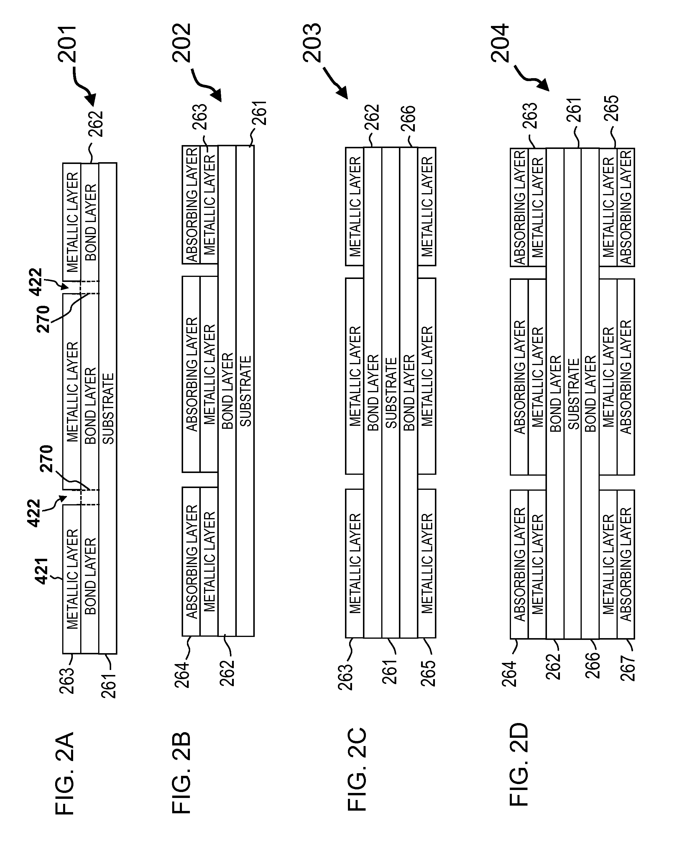
[0032]FIG. 2A is a cross-sectional diagram of film 201 along the line segment 2A-2A shown in FIG. 4A, according to some embodiments of the present invention. Film 201 includes substrate 261, bond layer 262 and metallic layer 263, wherein the bond layer 262 is used to connect the metallic layer 263 to the substrate 261. Substrate ...


PUM

PropertyMeasurementUnit
thicknessaaaaaaaaaa
thicknessaaaaaaaaaa
lengthaaaaaaaaaa

Abstract

Cable foil tape having random or pseudo-random patterns or long pattern lengths of discontinuous metallic shapes and a method for manufacturing such patterned foil tape are provided. In some embodiments, a laser ablation system is used to selectively remove regions or paths in a metallic layer of a foil tape to produce random distributions of randomized shapes, or pseudo-random patterns or long pattern lengths of discontinuous shapes in the metal layer. In some embodiments, the foil tape is double-sided, having a metallic layer on each side of the foil tape, and the laser ablation system is capable of ablating nonconductive pathways into the metallic layer on both sides of the foil tape.

Description

CROSS-REFERENCE TO RELATED APPLICATION[0001]This application claims priority to U.S. Provisional Application No. 61 / 157,067, filed Mar. 3, 2009, the subject matter of which is hereby incorporated by reference in its entiretyFIELD OF THE INVENTION[0002]The present invention is generally directed to communication cables and more specifically directed to mosaic tape having fixed, random and / or pseudo-random pattern lengths for use in communication cables, and manufacturing methods for producing mosaic tapes.INCORPORATION BY REFERENCE[0003]The present application incorporates by reference in their entireties the following U.S. Provisional Patent Applications:[0004]1. Ser. No. 61 / 034,312, filed Mar. 6, 2008 and entitled, “Communication Cable with Improved Crosstalk Attenuation.”[0005]2. Ser. No. 61 / 054,330, filed May 19, 2008 and entitled, “Communication Cable with Improved Crosstalk Attenuation.”[0006]3. Ser. No. 61 / 112,794, filed Nov. 10, 2008 and entitled “Communication Cable with Imp...

Claims


Application Information

Patent Timeline
Patent Type & Authority Applications(United States)
IPC IPC(8): H01B11/02
CPCB23K26/0846B23K26/18B23K26/409H01B13/26H05K1/0224H05K3/027H01B11/1008B23K26/40B23K2103/172Y10T29/49194H01B11/02H01B11/08H01B11/1025H01B11/085
Inventor JENNER, ROYAL O.HOUGHTON, II, TIMOTHY J.BOLOURI-SARANSAR, MASUDNORDIN, RONALD A.
Owner PANDUIT
Why Eureka
Try Eureka