[0050]In the present invention, the adsorption member (14, 15, 80) for controlling
air humidity, and the heating medium circuit (11) in which the heating fluid medium for heating or cooling the adsorbent of the adsorption member (14, 15, 80) are held together in the holding member (50), and the holding member (50) is configured to be drawn out of the casing (20). Therefore, according to the invention, the maintenance worker, etc., can remove the adsorption member (14, 15, 80) and the heating medium circuit (11) from the casing (20) by drawing the holding member (50) out, thereby allowing for easy maintenance of the adsorption member (14, 15, 80), and the components connected to the heating medium circuit (11). In drawing the holding member (50) out, detaching and reconnecting the pipes of the heating medium circuit (11) are not required. This can drastically improve the ease of maintenance of the humidity control apparatus.
[0051]According to the second aspect of the invention, the
refrigerant circuit (11) including the compressor (12) is held in the holding member (50). Therefore, the components, such as the adsorption member (14, 15, 80), the compressor (12), etc., can easily be removed the casing (20) without need of detaching and reconnecting the refrigerant pipes. According to the third aspect of the invention, the adsorption member is constituted of the adsorption
heat exchanger (14, 15), and is held in the holding member (50). This allows for easy removal of the components, such as the adsorption heat exchanger (14, 15), the compressor (12), etc., from the casing (20) without need of detaching and reconnecting the refrigerant pipes.
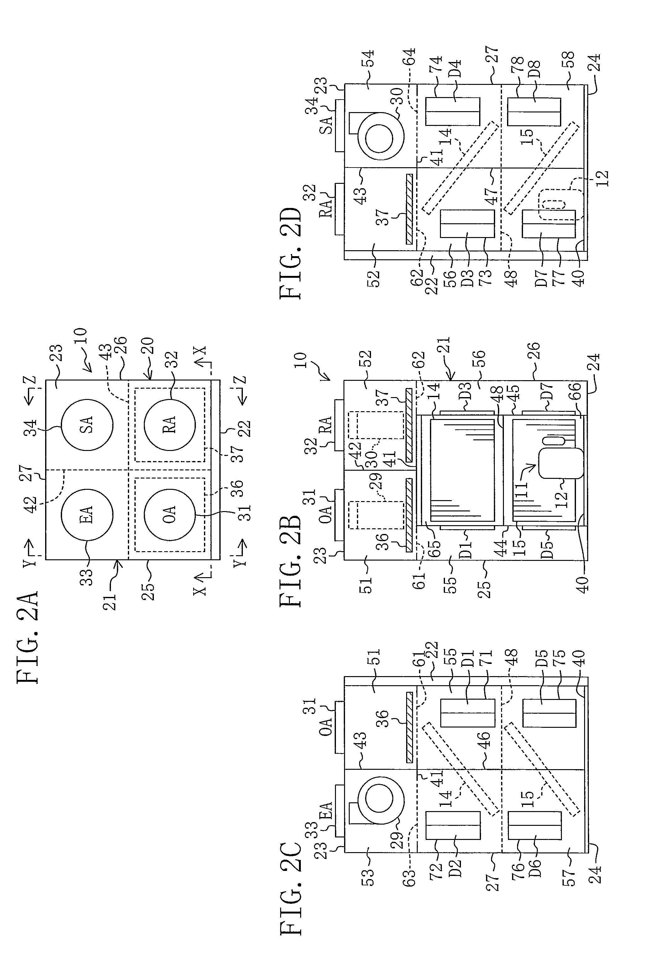
[0052]According to the fourth aspect of the invention, the compressor (12) is arranged in the humidity control chamber (65, 66) containing the adsorption heat exchanger (14, 15). This can reduce space for containing the compressor (12), and can downsize the casing (20). Further, since a distance between the compressor (12) and the adsorption heat exchanger (14, 15) is relatively reduced, the compressor (12) and the adsorption heat exchanger (14, 15) can be held together in the holding member (50), and can be drawn out of the casing together by a relatively simple structure.
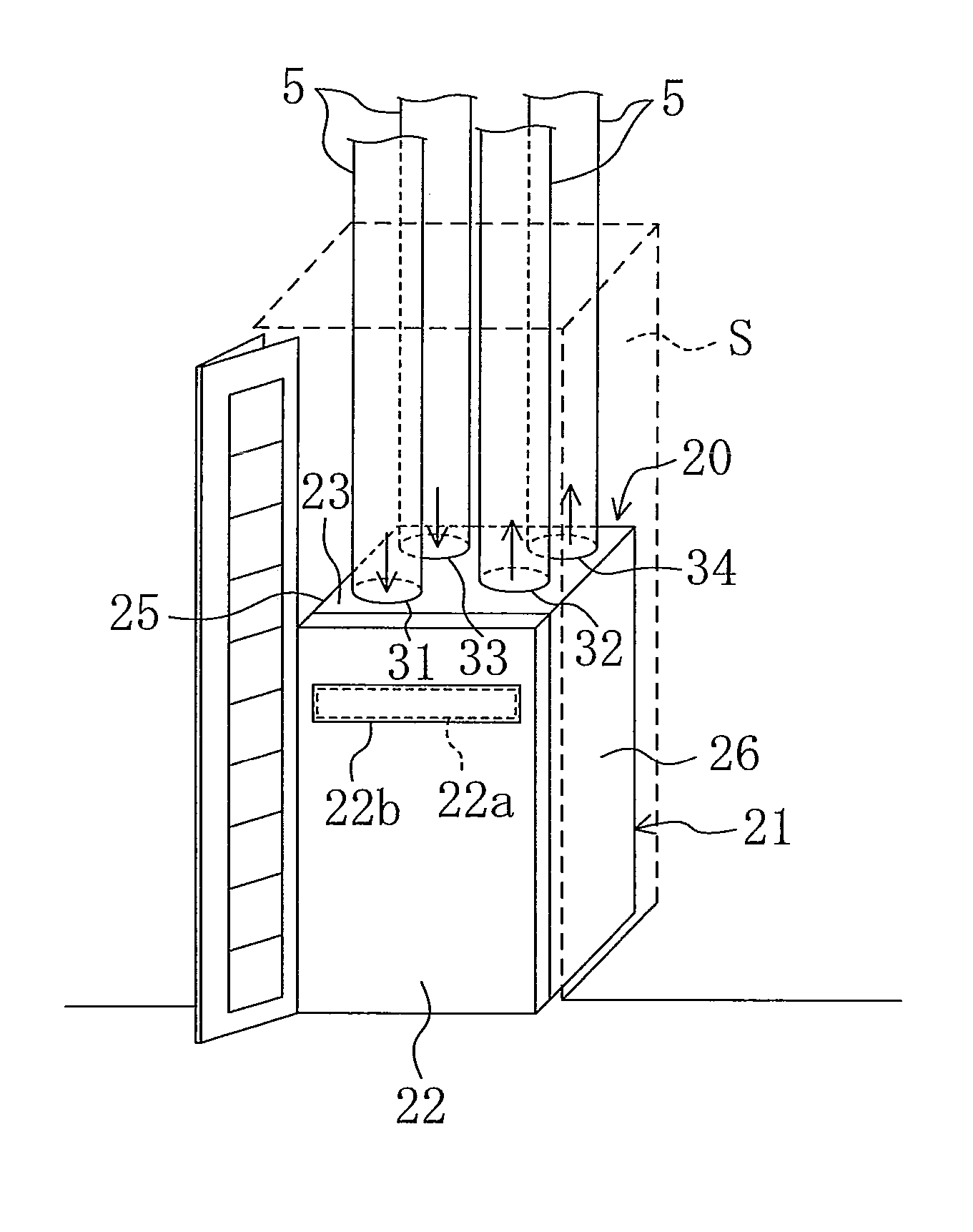
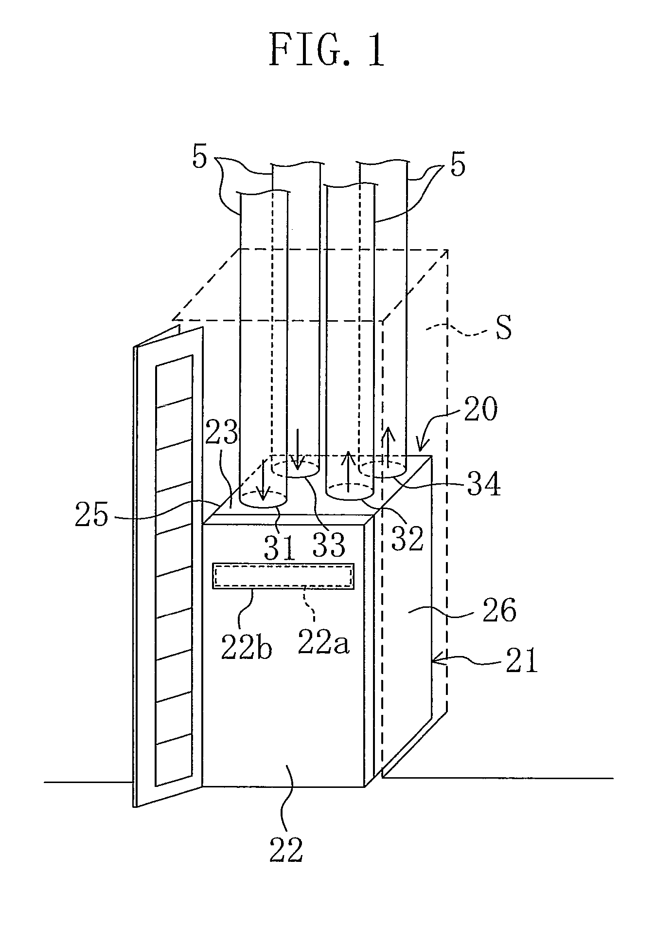
[0053]According to the fifth aspect of the invention, the outside air inlet port (31), the outward
discharge port (33), the room air inlet port (32), and the inward supply port (34) are formed in the upper surface of the casing (20). Therefore, the humidity control apparatus can be installed on the floor, and the ducts connected to the inlet ports (31, 32) and the
discharge and supply ports (33, 34) can extend upward (toward the ceiling). As a result, the ducts would not be routed horizontally around the humidity control apparatus installed on the floor, thereby drastically reducing space required for installation of the humidity control apparatus in the horizontal direction. Thus, the humidity control apparatus can be installed in limited space, such as in the
closet. The humidity control apparatus installed on the floor is easily maintained by the user, as compared with the humidity control apparatus installed on the ceiling.
[0054]Still according to the fifth aspect of the invention, the holding member (50) is configured to be drawn out of the casing (20) from the front side of the casing (20). Therefore, even if the humidity control apparatus is installed in the storage space, such as in the
closet, the holding member (50) can be drawn out from the opening side of the
closet, thereby allowing for easy maintenance of the adsorption member (14, 15, 80) and the heating medium circuit (11).
[0055]According to the sixth aspect of the invention, the outside air inlet port (31), the outward discharge port (33), the room air inlet port (32), and the inward supply port (34) are formed in the upper surface of the casing (20). Therefore, the humidity control apparatus can be installed on the floor, and the ducts connected to the inlet ports (31, 32) and the discharge and supply ports (33, 34) can extend upward (toward the ceiling). As a result, the ducts would not be routed horizontally around the humidity control apparatus installed on the floor, thereby drastically reducing space required for installation of the humidity control apparatus in the horizontal direction. Thus, the humidity control apparatus can be installed in limited space, such as in the closet. The humidity control apparatus installed on the floor is easily maintained by the user, as compared with the humidity control apparatus installed on the ceiling.
[0056]In particular, according to the seventh aspect of the invention, the humidity control chambers (65, 66) containing a plurality of adsorption heat exchangers (14, 15), respectively, are aligned in the vertical direction. This can alleviate
size increase of the casing (20) in the horizontal direction. Therefore, space for installation of the humidity control apparatus in the horizontal direction can be reduced to a further extent.
[0057]According to the eighth aspect of the invention, the divider plate (44, 45) providing the humidity control chamber (65, 66), and having the plurality of dampers (D1-D8) is provided on the side of the humidity control chamber (65, 66). This can prevent leakage of water condensed in the humidity control chamber (65, 66) outside the humidity control chamber (65, 66) through the dampers (D1-D8). If the divider plate (44, 45) is arranged on a lower side of the humidity control chamber (65, 66), a drain pan for receiving the
condensed water below the adsorption heat exchanger (14, 15) and the dampers (D1-D8) of the divider plate (44, 45) may interfere with each other. However, with the divider plate (44, 45) provided on the side of the humidity control chamber (65, 66), sufficient space for installation of the drain pan is ensured below the adsorption heat exchanger (14, 15).
[0058]According to the ninth aspect of the invention, the divider plate (44, 45) is provided on the lateral side of the humidity control chamber (65, 66), and is configured to move back and forth. Therefore, with the
front cover (22) detached from the casing body (21), the divider plate (44, 45) can easily be drawn forward, thereby allowing for easy maintenance of the plurality of dampers (D1-D8).
[0059]According to the tenth aspect of the invention, the supply fan (30) and the discharge fan (29) are provided above the humidity control chamber (65, 66) in such a manner that the fans (29, 30) are positioned relatively close to the outside air inlet port (31) and the room air inlet port (32). This can reduce air flow resistance of the supply fan (30) and the discharge fan (29), and can reduce power required by the fans.
[0060]According to the eleventh aspect of the invention, the compressor (12) of the refrigerant circuit (11) is arranged below the humidity control chamber (65, 66). This can lower the center of gravity of the humidity control apparatus. Therefore, the humidity control apparatus can be installed on the floor in a relatively
stable state. As compared with the case where the compressor (12) is arranged at a relatively high position, the compressor (12) can easily be placed in / removed from the casing, and can easily be maintained.
[0061]According to the twelfth aspect of the invention, with the
front cover (22) detached from the casing body (21), the adsorption heat exchanger (14, 15), the supply fan (30), the discharge fan (29), the compressor (12), and the filter (36, 37) can be removed from the casing from the front side of the casing (20) for the maintenance. In particular, when the humidity control apparatus is contained in the closet, etc., sufficient space for maintenance cannot easily be ensured behind or on the side of the apparatus. However, according to the present invention, every component can be removed from the front side of the casing, thereby allowing for easy maintenance of them.
[0062]According to the thirteenth and fourteenth aspects of the invention, the room air inlet port (32) and the outside air inlet port (31) are arranged in the front portion of the casing (20), and the first filter(36) and the second filter (37) are arranged below the inlet ports (31, 32). Therefore, with the
front cover (22) detached from the casing body (21), the first filter (36) and the second filter (37) can easily be drawn forward, thereby allowing for easy cleaning and replacement of the filters by the user, etc.

