
Rectifier applicable in high temperature condition

a rectifier and high temperature technology, applied in the direction of diodes, semiconductor devices, electrical apparatus, etc., can solve the problems of high reverse leakage current of schottky diodes and inability to operate in high temperature conditions, and achieve high reverse surge capability, low forward voltage, and high efficiency

Inactive Publication Date: 2010-09-09
ACTRON TECH
View PDF9 Cites 1 Cited by
  • Summary
  • Abstract
  • Description
  • Claims
  • Application Information

AI Technical Summary

Benefits of technology

[0007]The primary objective of the present invention is to provide a rectifier applicable in high temperature condition. The rectifier has properties of low forward voltage (VF) and low reverse leakage current (IR) so that the rectifier can be applied in high temperature condition with high efficiency. Furthermore, the rectifier has structures for decreasing the accumulation of electric field so that the rectifier can have high reverse surge capability.
[0010]The rectifier has properties of low VF and low IR so that the rectifier can be applied in high temperature condition. Furthermore, the rectifier has structures for decreasing the accumulation of electric field so that the rectifier can survive in a reverse bias condition. Therefore, the diode is protected from failure of high reverse bias.

Problems solved by technology

However, the Schottky diode has a higher reverse leakage current.
Accordingly, Schottky diode is not suitable for operation in the high temperature condition.

Method used


Image

  • Rectifier applicable in high temperature condition
  • Rectifier applicable in high temperature condition
  • Rectifier applicable in high temperature condition

Examples


Embodiment Construction

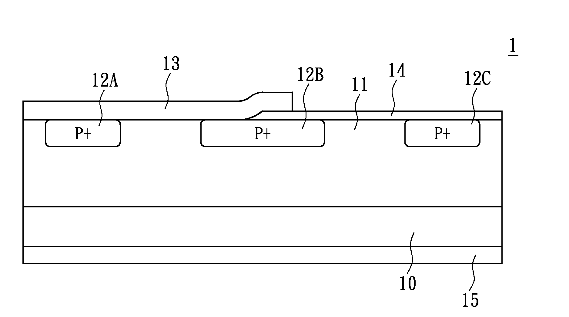
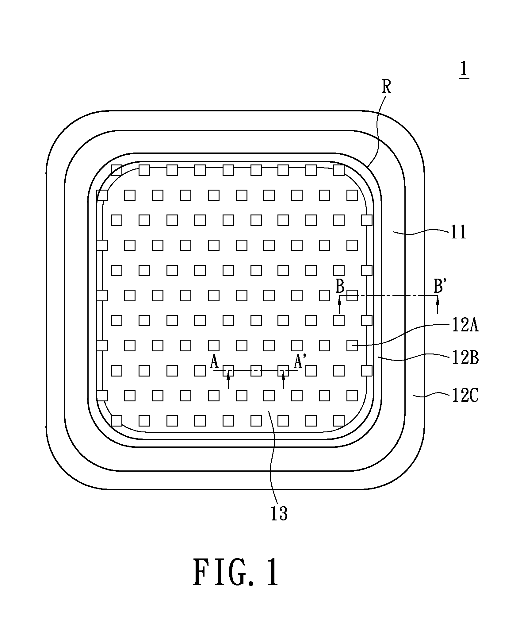
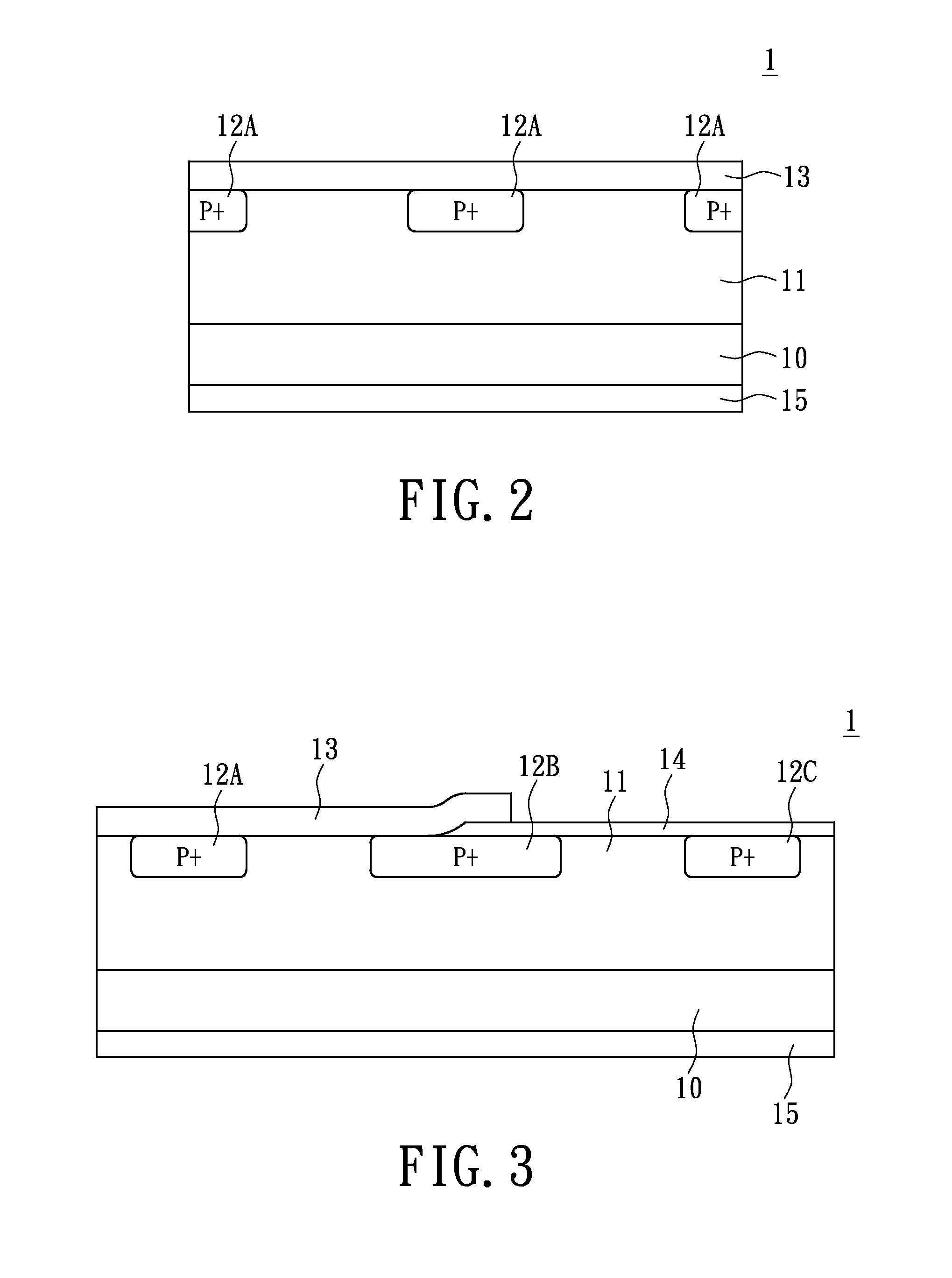
[0022]Please refer to FIG. 1, the present invention provides a rectifier 1 which can be used under high temperature application. The rectifier 1 provides high efficiency in high temperature operation and high reliability in high reverse bias condition. The rectifier 1 has a conductive semiconductor layer 10 having an upper surface 101 and a lower surface 102 (as shown in FIG. 6), a conductive epitaxial layer 11, a plurality of conductive doped region 12A, a fringe conductive doped region 12B, at least one outer fringe conductive doped region 12C, a first metal layer 13, and a second metal layer 15 (shown in FIGS. 2 and 3).

[0023]FIG. 1 shows a top view of the first preferred embodiment of a rectifier according to the present invention. The conductive semiconductor layer 10 and the conductive epitaxial layer 11 are N-type. The conductive semiconductor layer 10 is referenced as N+ and the conductive epitaxial layer 11 is referenced as N in accordance to the doping concentration. On the...


PUM

PropertyMeasurementUnit
temperatureaaaaaaaaaa
forward voltageaaaaaaaaaa
temperatureaaaaaaaaaa

Abstract

A rectifier for high temperature application includes a conductive semiconductor layer, a conductive epitaxial layer, and a plurality of conductive doped regions within the conductive epitaxial layer. A fringe conductive doped region is formed surrounding the conductive doped region, and an outer fringe conductive doped region is formed further surrounding the fringe conductive doped region. A first metal layer is formed on the upper surface of the conductive semiconductor substrate covering the entire conductive doped regions, and contacting at least a portion of the fringe conductive doped region. A second metal layer is formed on the lower surface of the conductive semiconductor substrate.

Description

BACKGROUND OF THE INVENTION[0001]1. Field of the Invention[0002]The present invention relates to a rectifier applicable for high temperature condition, in particular to a rectifier with high reverse surge capability for high temperature condition.[0003]2. Description of Related Art[0004]With the development of semiconductor technology, diodes are commonly used for power devices. For example, PN junction diode is applied in alternator system for rectification. PN junction diode has property of low reverse leakage current, but high forward voltage (VF). During operation for a PN junction diode, the value of VF is about 1V so that more energy is consumed in the application.[0005]On the other hand, Schottky diode is another type of diode with a much lower VF than the PN junction diode. However, the Schottky diode has a higher reverse leakage current. Accordingly, Schottky diode is not suitable for operation in the high temperature condition.[0006]Therefore, in view of the above mentione...

Claims


Application Information

Patent Timeline
Patent Type & Authority Applications(United States)
IPC IPC(8): H01L29/86
CPCH01L29/0619H01L29/8611H01L29/66136
Inventor SHEEN, CHARNG-KENGLU, CHIEN-CHIH
Owner ACTRON TECH
Learn More