Mini bike having pedal as a power generator

a pedal and pedal technology, applied in the field of mini bikes, can solve the problems of inconvenient driving method, easy wear of the brake pad, and the difficulty of children skillfully riding on the quick

Inactive Publication Date: 2010-09-09
KIM MI NAR
View PDF9 Cites 10 Cited by
  • Summary
  • Abstract
  • Description
  • Claims
  • Application Information

AI Technical Summary

Benefits of technology

[0016]According to the present invention, as a user rides on a mini bike by stamping a pedal, the mini bike can be driven with a speed appropriate for a taste and a body condition of the user, because it is manufactured in a small size, the mini bike can be enjoyed by simply carrying almost regardless of time and place, for example, when ...

Problems solved by technology

Such a driving method is inconvenient because the user should continue to push the ground with the foot.
Particularly, because the quick board has a small width, length and a small wheel, there is a problem that much time is required for children to skillfully ride on the quick board and a safety accident may occur in a process of learning to ride on the quick board.
When the user drives the gear by pressing the pedal 31, after the driving is started, a force for pressing the pedal is easily obtained, however, because the user cannot intentionally adjust a speed, a brake should be used in order to reduce a driving speed of the wheel after accelerating a speed and thus a pad of the brake is easily worn, and when traveling up on the hill with the bike, a traveling speed does not increase.
In Registered Korean Patent No. 0553134 having the above-described configuration, because a user should move a handle while operating the board like a seesaw, a balance of a waist, leg...

Method used


Image

  • Mini bike having pedal as a power generator
  • Mini bike having pedal as a power generator
  • Mini bike having pedal as a power generator

Examples


Embodiment Construction

[0066]An exemplary embodiment according to the present invention is described hereinafter in detail.

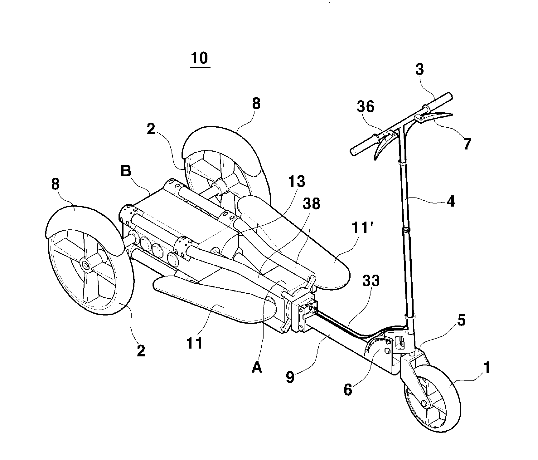
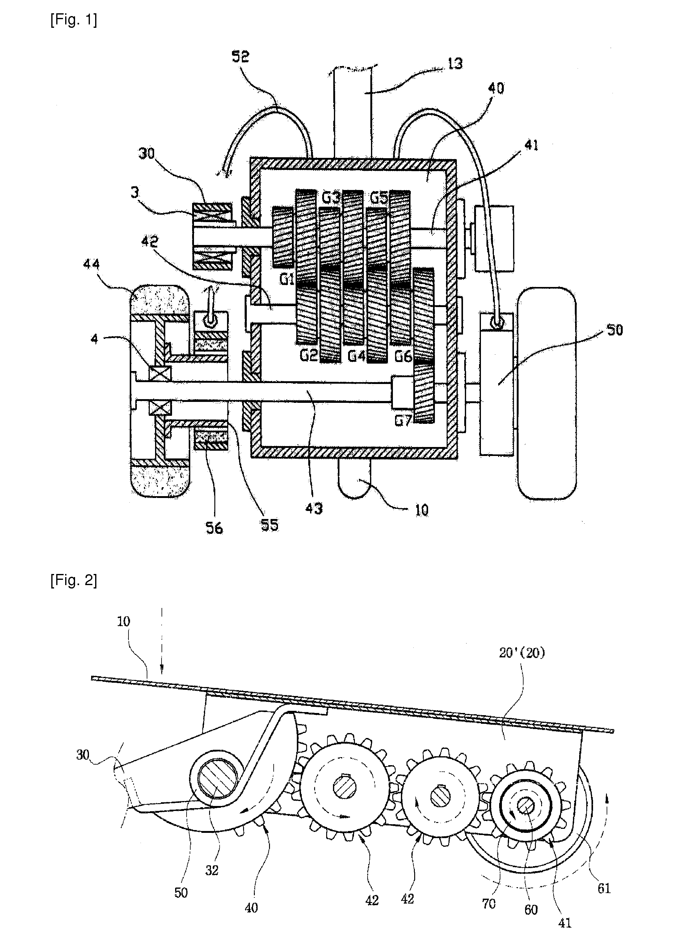
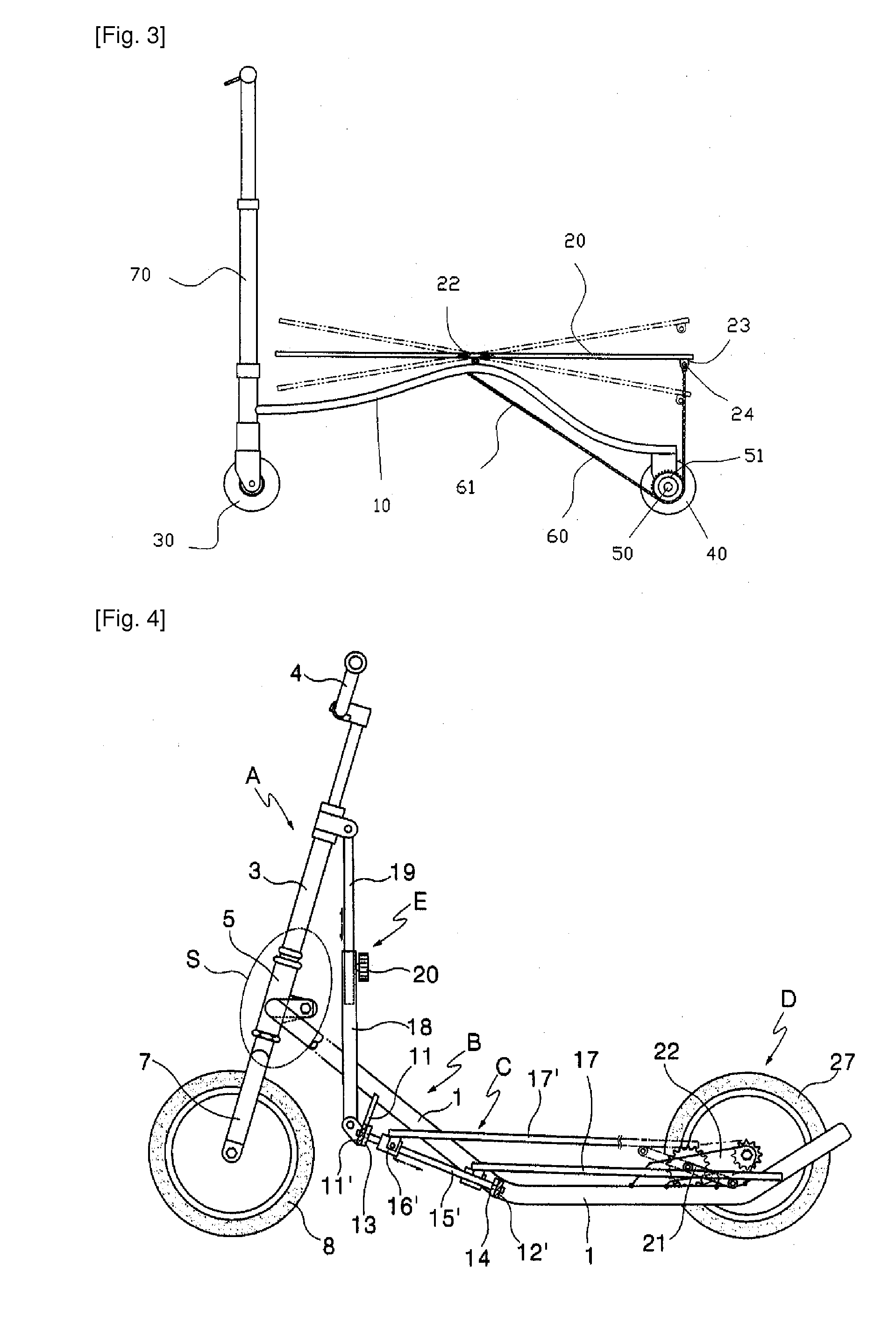
[0067]A mini bike having a pedal as a power generator that has a handle 3 in an upper part in order to steer a front wheel 1, and that connects a front wheel 1 side and a rear wheel 2 to a bike body 9, and that drives the wheels by operating a pedal connected to a plurality of gears, and that adjusts a speed thereof using a brake handle 7 installed in the handle 3 includes: a driver A that connects a pedal shaft between both pedals 11 and 11′ and in which a spring 16 is installed at the inside of a connector of both sides of the pedal shaft 12 to which the both pedals 11 and 11′ are connected, and in which one end of the shaft 13 and the pedal shaft 12 are connected to a first bevel gear 14 in order to transmit rotation power generated by a vertical rolling motion due to an elastic force of the spring 16; a second bevel gear 22 installed to connect the other side end of the shaft 13 a...


PUM


Abstract

A mini bike for strengthening a leg muscle, and for enjoying amusement and a leisure time is provided. The mini bike having a pedal as a power generator includes: a driver having a first bevel gear in order to transmit rotation power generated by a rolling motion of a pedal; a second bevel gear installed to transmit rotation power generated in the driver; a first power transmission gear coaxially installed in the second bevel gear to transmit rotation power to a spline shaft; a clutch positioned at the spline shaft to selectively connect rotation power of the first power transmission gear to a first gearshift and a second gearshift and for controlling a low speed and a high speed; a first driving gear and a second driving gear for rotating by selection of the clutch; and a driving controller including a gearshift in which the clutch is connected to the cable in order to select the first gearshift and the second gearshift. Therefore, when young boys and girls go to or coming from a school, when office workers go to or come from their office, when an adult enjoys a leisure time, as well as when children enjoy amusement, the bike can be used, and when riding on the bike, the user can enjoy a low speed or a high speed, and the bike can be used for strengthening a leg muscle.

Description

TECHNICAL FIELD[0001]The present invention relates to a mini bike of a quick board form used for strengthening a leg muscle and for amusement, and more particularly, to a mini bike including a driver having a handle and a plurality of wheels and to be driven by a pedal and a driving controller for transmitting rotation power generated by the driver to the wheels in a low speed or a high speed such that when young boys and girls go to or coming from a school, when office workers go to or come from their offices, when an adult enjoys a leisure time, as well as when children enjoy amusement, the bike can be used, and when riding on the bike, the user can enjoy a low speed or a high speed and can easily ride on the bike even in a hilly area, and the bike can be used for strengthening a leg muscle.[0002]Nowadays, people enjoying a mini bike of a motorcycle form increase, however there is a defect that the mini bike of a motorcycle form can be driven by only a person who can drive a motor...

Claims


Application Information

Patent Timeline
IPC IPC(8): B62M1/04B62M1/24
CPCB62K3/002B62M1/30B62M11/10Y10T74/19205Y10T74/1503Y10T74/19465B62M17/00B62K17/00B62M7/00F16H57/038
Inventor KIM, MI NAR
Owner KIM MI NAR
Why Eureka
Try Eureka