
Vehicle concealed antenna

a technology for concealed antennas and vehicles, applied in the field of vehicle antennas, can solve the problems of high rf exposure levels, low cost, and inability to disguise antennas, and achieve the effects of low cost, convenient installation and small siz

Inactive Publication Date: 2010-09-09
SINCLAIR TECH
View PDF24 Cites 15 Cited by
  • Summary
  • Abstract
  • Description
  • Claims
  • Application Information

AI Technical Summary

Benefits of technology

[0016]The present invention provides an improved antenna assembly for use in a vehicle in a concealed fashion. Unlike prior art antennas, the present invention provides an antenna assembly that has the advantages of low cost, ease of installation, small size, and direct integration with a tunable matching circuit.
[0021]The tunable matching circuit provides a means to optimize the antenna performance, which is especially important for concealed vehicle antennas because differences in bumper or vehicle body geometry and size and also the mounting position of the antenna can have a significant impact on the antenna performance. The matching circuit is preferably a LC circuit, and the tuning means is preferably a tuning screw of a capacitor trimmer. The tuning circuit is preferably contained in the housing in such a way that the capacitors are in shunt and that the capacitor trimmers can be mounted on the antenna base wall, thereby allowing a tuning screw to be accessed from outside of the housing.

Problems solved by technology

However, the major disadvantage of this design is that as many modern vehicles no longer use traditional AM / FM antennas, and such a disguise will likely no longer be possible in the near future.
However, this type of antenna is also not commonly used in modern vehicles.
However, this antenna has the disadvantage of high RF exposure levels when functioning as a transmitter antenna.
Additionally, this type of antenna is not easily concealed.
However, these antennas are small and low profile antennas and are typically used for GPS and cellular applications.
These antennas cannot be converted for lower frequency band applications such as VHF and UHF systems.
However, such antennas cannot handle sufficiently high power to operate as a transmitter antenna, and also do not comply with many RF safety regulations.
The design of hidden antennas presents several design challenges, and one must strive to optimize the following features: antenna efficiency, omni-directivity, low RF exposure, universality, compact antenna size, and material and installation cost.
However this kind of antenna can only be useful in low power and short range applications, where antenna efficiency and omni-directivity can be compromised.
Since the license plate is exposed and close to the ground, the reliability and durability are questionable under snow, ice, salt and other extreme weather conditions.
While the aforementioned patent teaches the matching of the antenna by cutting cable stub lengths, it is readily found that this is a very difficult method for tuning the antenna to a desired frequency.
Another concern is that it is difficult to balance the feed cable, which can cause unbalanced current flowing on the shield of the coaxial cable.
This in turn will reduce the antenna efficiency, increase the antenna noise and make the antenna unstable.
Furthermore, when multiple antennas are required for improved omni-directionality and diversity purposes, this type of antenna can be used only for vehicles that have both front and rear license plates and limits the maximum number of antennas to two.
The major drawback of this antenna is that it is horizontally polarized.
In particular, if this type of designs is used in land mobile radio systems, considerable signal drop is expected when the mobile system is communicating with the base station where signals are generally transmitted vertically.
Since the conductive surface is comparatively large for many land mobile radio systems, significantly altering the foam may present regulatory and liability concerns.
However the conductive surface embedded inside the bumper, and especially the slot formed between the conductive surface and the vehicle body, may be susceptible to distortion easily, which may impair the performance of the antenna.
The antenna alignment proposed in the prior art results in poor coverage when single antenna is implemented, as noted in other designs discussed above.
Unfortunately, this design is only applicable for reception antennas.

Method used


Image

  • Vehicle concealed antenna
  • Vehicle concealed antenna
  • Vehicle concealed antenna

Examples


example

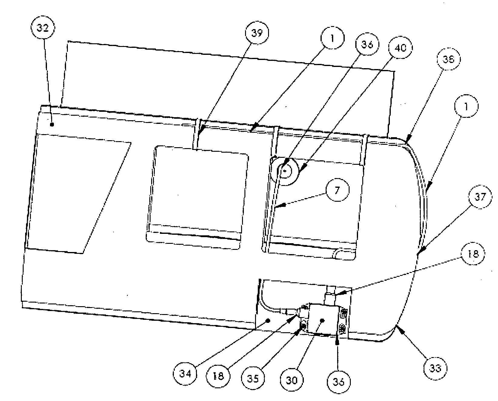
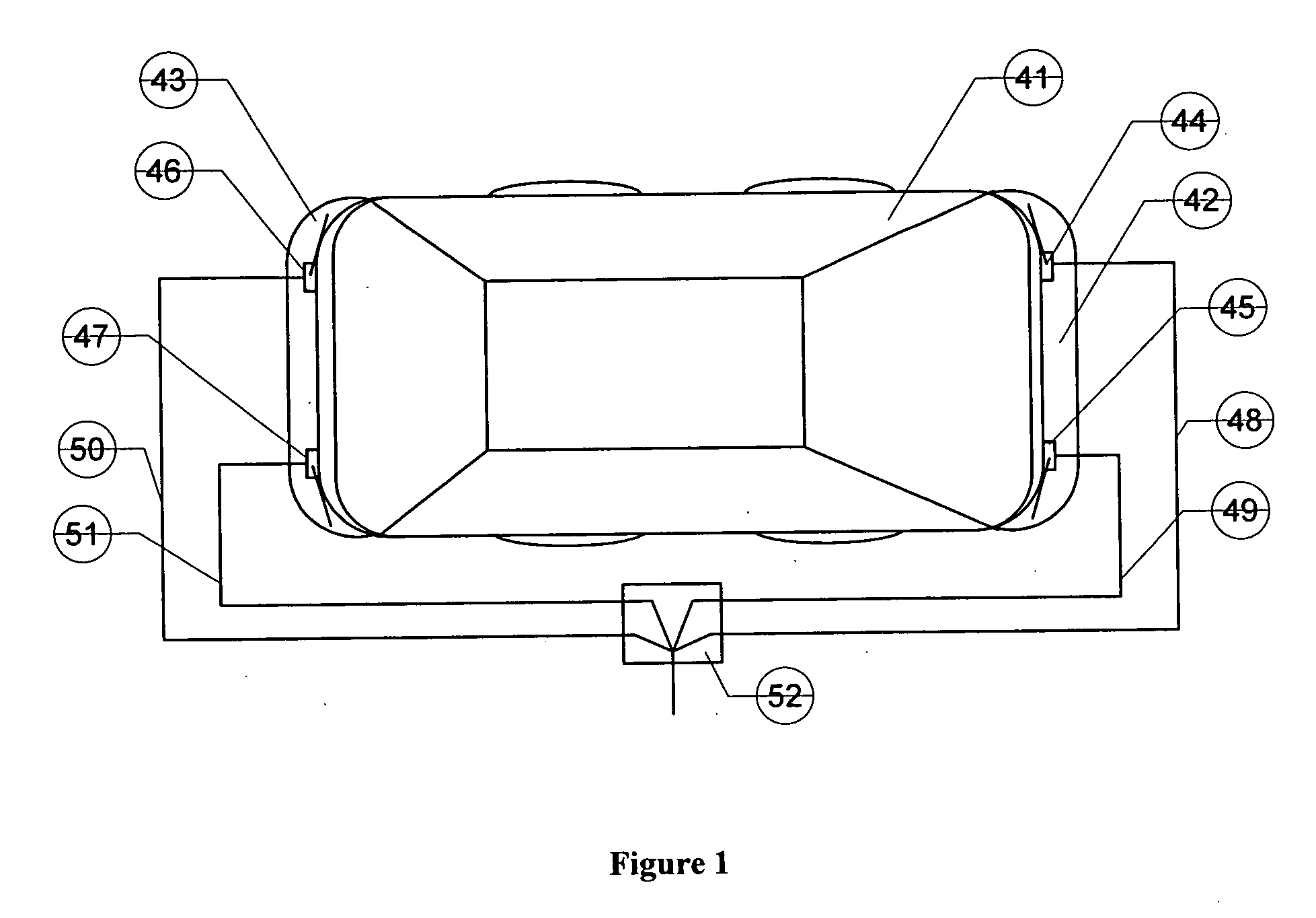
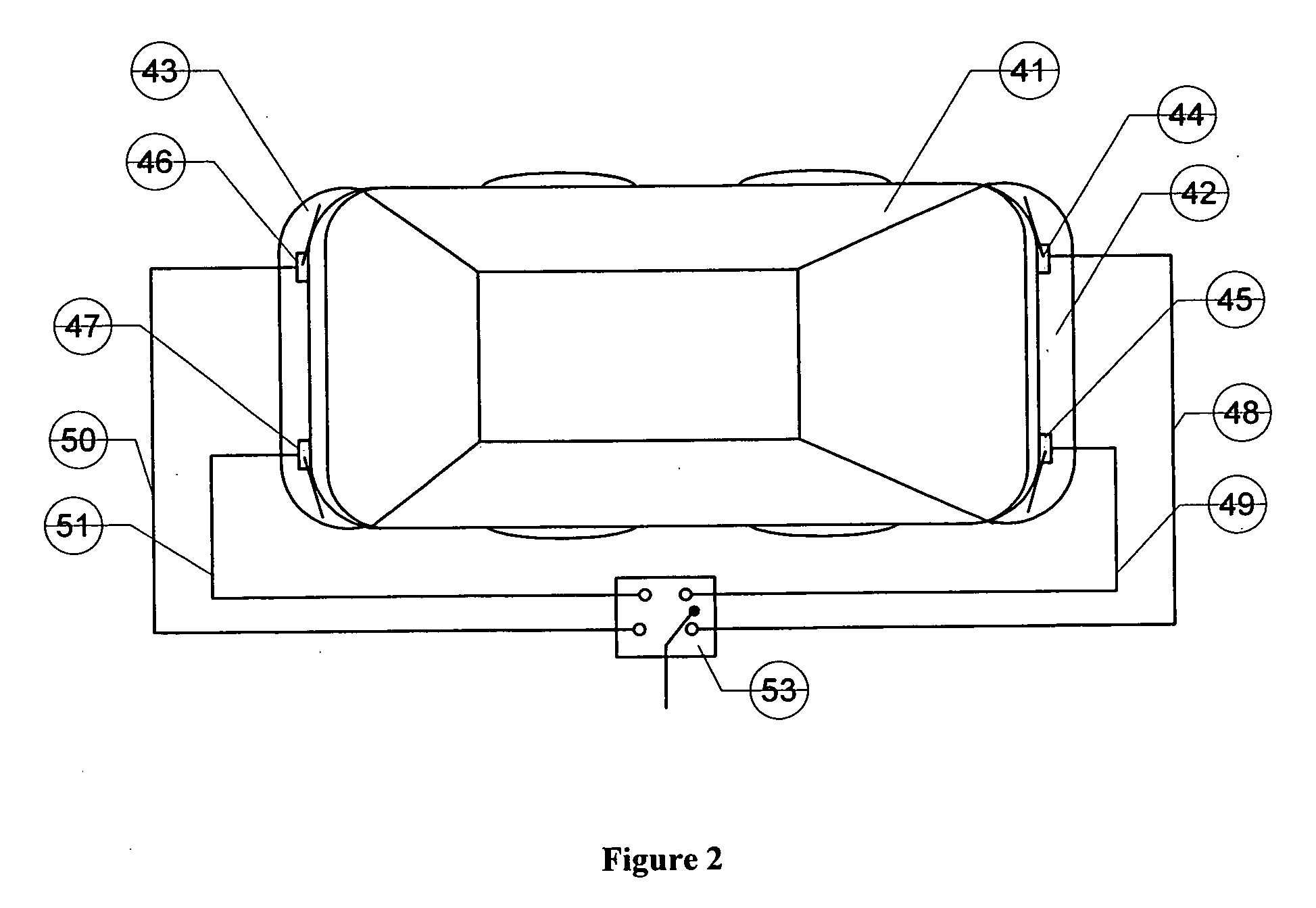
[0059]In the following example, a preferred embodiment is provided in which an integrated antenna assembly is disclosed for concealment within a bumper or non-metallic fender. Referring to FIGS. 4 through 10, the vehicle mounted concealed antenna system disclosed herein includes an antenna radiator 1 (FIG. 5) or 2 (FIG. 6), and a matching circuit network consisting of two capacitor trimmers 3, 4, inductor coils 5 (shown in FIG. 10), environmentally sealed metal mounting base 6 (referred to in the preceding discussion as a housing), feed cable 7 and feed connector 8, antenna output connector 9. The female connectors 8 and 9 are arranged and mounted by hex nuts 10 and o-ring seals 11 into the walls of the mounting base 6.

[0060]A detailed view of a preferred embodiment of the antenna radiator is shown in FIG. 7. The antenna radiator 1 consists of a copper wire 12, dielectric sleeve 54, male connector 13, two copper ferrules 14, braided wire 55, outer jacked 56, and shrink tubing 15.

[00...


PUM

PropertyMeasurementUnit
flexibleaaaaaaaaaa
dielectricaaaaaaaaaa
shapeaaaaaaaaaa

Abstract

An antenna assembly for use in a vehicle is provided, whereby the assembly is preferably concealed within a vehicle bumper or non-conductive fender. The assembly includes a flexible antenna radiator directly connected with an output of a tunable matching circuit contained within a housing, whereby the housing further provides a connection means between the input of the matching circuit and a radio system in the vehicle. The matching circuit is tunable by control means provided externally on the housing, enabling the antenna assembly to be easily tuned prior to or during installation. The inventive antenna assembly advantageously provides a low cost antenna with ease of installation, small size, and direct integration with a tunable matching circuit.

Description

FIELD OF THE INVENTION[0001]The invention relates to a vehicle antenna for radio frequency signal transmission and reception. More particularly, the invention relates to a compact antenna assembly for concealment within a vehicle bumper.BACKGROUND OF THE INVENTION[0002]Concealed antennas are used in vehicles for a number of applications, including the public safety applications such as the disguising of police car antennas and aesthetic applications in the general automotive market. Antennas of this type are generally known as disguised, concealed or hidden antennas.[0003]There are, in general, two main types of concealed antennas. The first type is the covert antenna, which is visible but cannot be distinguished from a regular antenna. An example of a covert antenna is converting the traditional fender mount or roof mount AM / FM radio antennas to VHF or UHF land mobile radio antennas. The second type of a concealed antenna is a hidden antenna, where the antenna is hidden within or u...

Claims


Application Information

Patent Timeline
Patent Type & Authority Applications(United States)
IPC IPC(8): H01Q1/50H01Q1/32
CPCH01Q1/3283Y10T29/49826H01Q9/30
Inventor LAN, KANGGUO, HARRYKOIVUNEN, JANRIEMANN, RUDOLF F.
Owner SINCLAIR TECH
Learn More