Temporally Aligned Exposure Bracketing for High Dynamic Range Imaging

a technology of dynamic range and exposure bracketing, applied in the field of imaging systems, can solve the problems of not being able to solve the problem of point and shoot cameras, computer algorithms, and not being able to solve the problem of normal exposure or even a digitally enhanced exposure, and not being able to resolve all image areas

Inactive Publication Date: 2010-09-09
WAGNER PAUL A
View PDF29 Cites 46 Cited by
  • Summary
  • Abstract
  • Description
  • Claims
  • Application Information

AI Technical Summary

Benefits of technology

[0039]In a still different embodiment, the prism is capable of splitting the image into four or more levels of e...

Problems solved by technology

HDRI is most commonly employed in situations where the range between light and dark areas is great, and subsequently a normal exposure, or even a digitally enhanced exposure, are not adequate to resolve all of the image area.
The real challenge with HDRI is not the file formats or computer algorithms to tone map them to 8-bit displays.
The hardest part of capturing HDR images is the physical devices used to capture the imagery.
They are not point and shoot cameras and are not capable of motion photography.
Both of these techniques have substantial disadvantages.
The second technique can be done with conventional hardware, but it is time consuming and takes substantial expertise to pull off.
In addition, because the images are not temporally aligned, meaning they were taken one after another at different moments in time, there can be changes in the scene that produce artifacts when the HDRI software attempts to eliminate or synthesize the objects in motion across the frame.
As such this technique is totally useless for motion photography and can only be used with substantial success in still photography applications.
For this reason, exposure bracketed HDRI is typically restricted to still subjects, and any animals, cars, pedestrians, moving leaves or litter, clouds, etc., in fact anything that is shifting within the frame will preclude HDRI, or at the very l...

Method used


Image

  • Temporally Aligned Exposure Bracketing for High Dynamic Range Imaging
  • Temporally Aligned Exposure Bracketing for High Dynamic Range Imaging
  • Temporally Aligned Exposure Bracketing for High Dynamic Range Imaging

Examples


Embodiment Construction

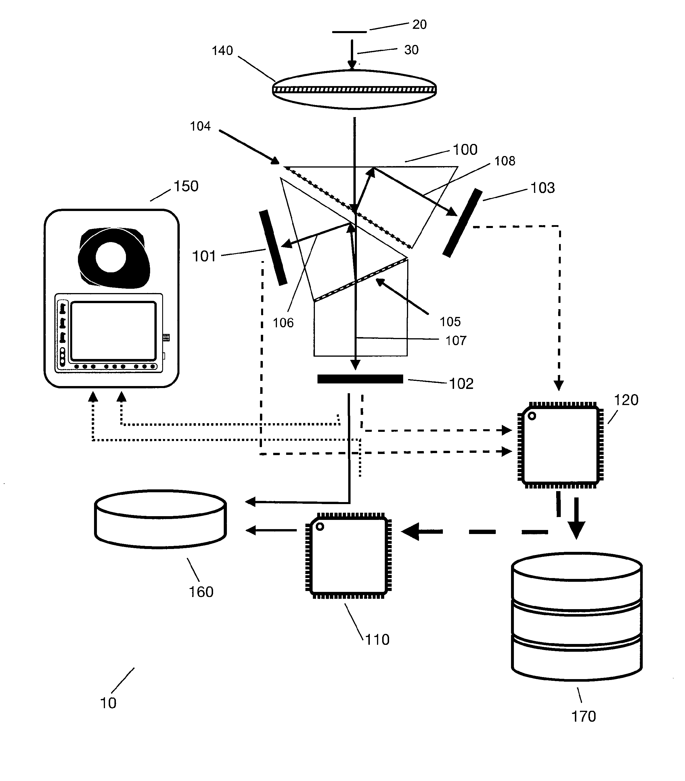
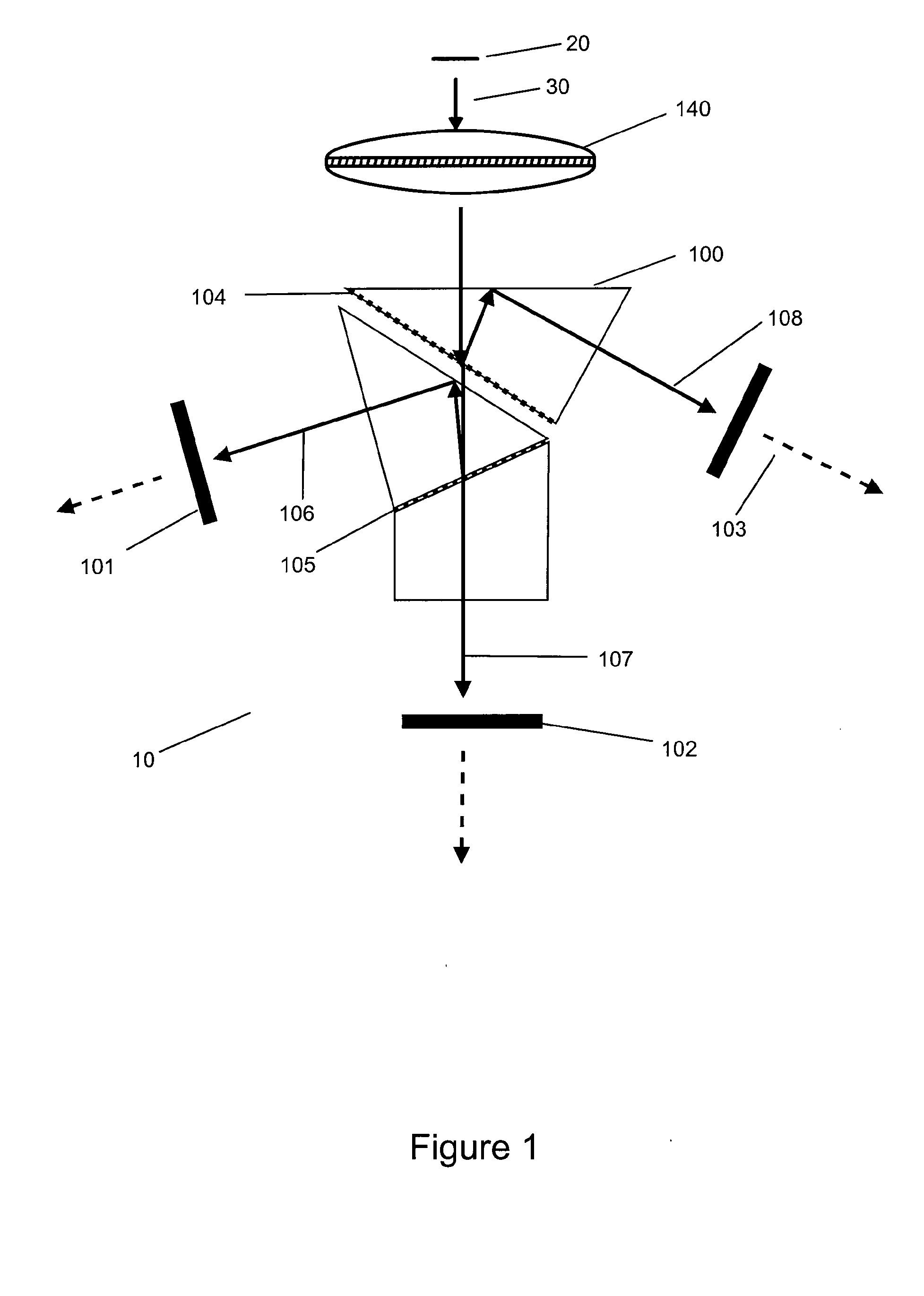
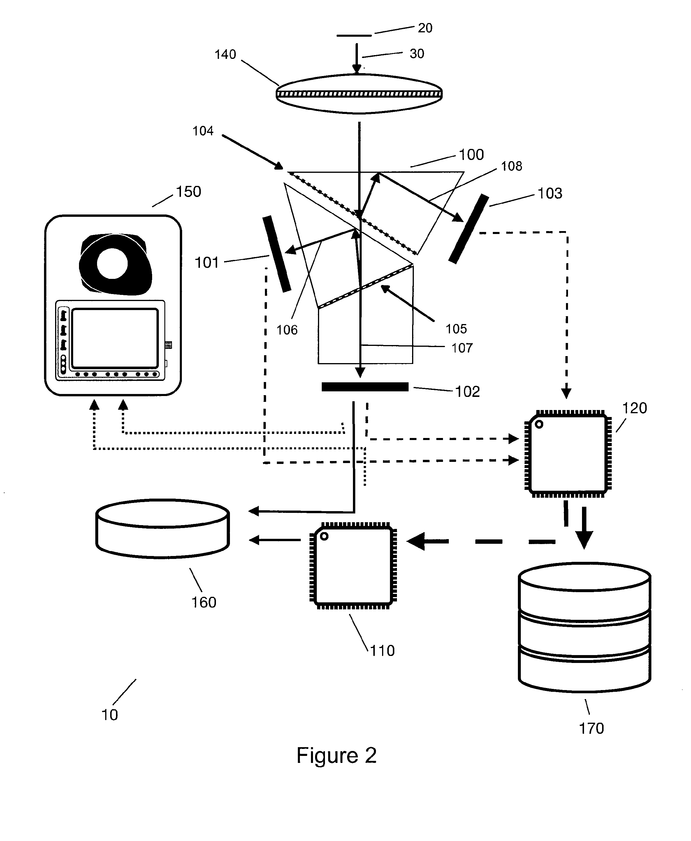
[0050]The optical imaging system of the present invention provides an improvement to high dynamic range imaging, and assemblies therefore, that allows temporally aligned exposure bracketing. The system is simple, elegant, leverages existing technologies, allows for motion capture with no temporal distortion, and is relatively inexpensive to implement.

[0051]The present optical imaging system allows the user to capture light with confidence that the under and over exposed regions in the image will be imaged properly. The user simply captures all the available light with and image capturing device, and determines later how to map that information to the output device. With the optical imaging system the user can create stunning imagery that is otherwise impossible to capture, even with the most sophisticated of the current generation of normal photography equipment.

[0052]Before the present invention is described in greater detail, it is to be understood that this invention is not limit...


PUM


Abstract

The invention provides an optical imaging system for temporally aligning bracketed exposures of a single image, the system comprising a light aperture, a prism and a image capturing device, where the prism is capable of splitting an incoming image from the light aperture into at least two temporally aligned images, and where the image capturing device captures the temporally aligned images at different levels of exposure.

Description

REFERENCE TO RELATED APPLICATION[0001]This application claims the benefit of U.S. Provisional Patent Application No. 61 / 157,494, filed Mar. 4, 2009, the complete disclosure of which is incorporated herein, in the entirety.COPYRIGHT NOTICE[0002]A portion of the disclosure of this patent document contains material which is subject to copyright protection. The copyright owner has no objection to the facsimile reproduction by anyone of the patent document or the patent disclosure, as it appears in the United States Patent and Trademark Office patent files and records, but otherwise reserves all other copyright rights.BACKGROUND OF THE INVENTION[0003]1. Field of the Invention[0004]This invention relates generally to imaging systems, and more particularly, to imaging systems that provide varying exposures for production of high dynamic range images.[0005]2. Description of Related Art[0006]High dynamic range imaging (HDRI) is a term applied in image processing, computer graphics and photog...

Claims


Application Information

Patent Timeline
IPC IPC(8): H04N5/235
CPCH04N5/2254H04N5/2356H04N5/2355H04N5/235G02B27/1066G02B27/144H04N23/70H04N23/743H04N23/741G03B7/093G03B17/02
Inventor WAGNER, PAUL A.
Owner WAGNER PAUL A
Why Eureka
Try Eureka