Characterising eye-related optical systems

a technology of optical systems and optical components, applied in the field of optical components of eye-related optical systems, can solve the problems that inaccuracy is unlikely to make this worthwhile, and achieve the effect of length of ey

Inactive Publication Date: 2010-09-09
BRIEN HOLDEN VISION INST (AU)
View PDF0 Cites 14 Cited by
  • Summary
  • Abstract
  • Description
  • Claims
  • Application Information

AI Technical Summary

Benefits of technology

[0023]Because an interrogating beam will encounter multiple interfaces between materials of different optical characteristics as it travels into the eye-related system, the respective returned beam will be composed of a set of component returned beams. The component returned beam which is generally of most interest is that returned from the retina (the rear-most interface of the eye-related system) because this provides the longest beam path in the eye. Fortunately, the component beams returned from the cornea and retina are also usually the most intense and/or distinct. While component beams returned from other surfaces within the eye-related system are more difficult to detect and distinguish from one another, the technique of the present invention allows for such component returned beams to be selected for analysis. Selection and comparison of return beam components associated with both the cornea and the retina will allow the length of the eye to be determined using interferometric methods, eye length being of critical interest for the monitoring of myopia progression.
[0024]Interferometric measurement of eye length may be combined with the mapping of refractive aberrations of an eye with particular advantage where a scanning illuminatin

Problems solved by technology

A deflector element may be moveable from location to location within the array to cover multiple angles but the added complication and inaccuracies are not likely to make this worthwhile.
However, scanning an illuminating beam from one array

Method used


Image

  • Characterising eye-related optical systems
  • Characterising eye-related optical systems
  • Characterising eye-related optical systems

Examples


Embodiment Construction

[0029]Having portrayed the nature of the present invention, particular examples will now be described with reference to the accompanying drawings. However, those skilled in the art will appreciate that many variations and modifications can be made to the examples without departing from the scope of the invention as outlined above.

DESCRIPTION OF THE SEVERAL VIEWS OF THE DRAWINGS

[0030]In the accompanying drawings:

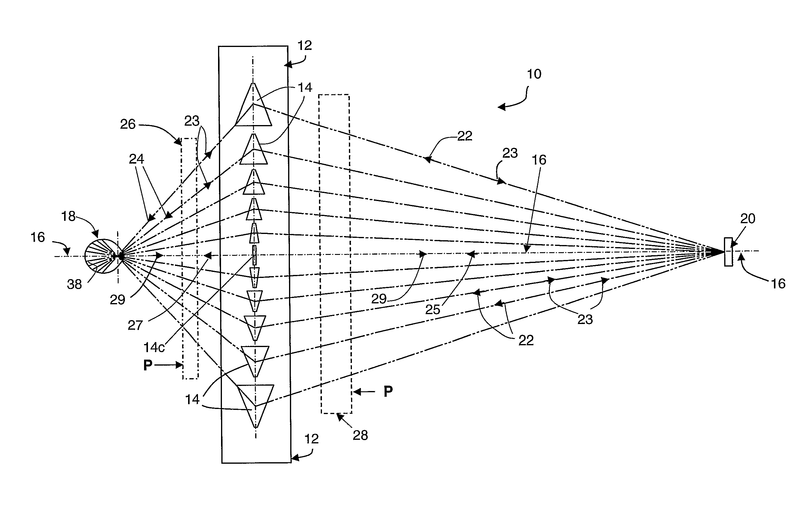
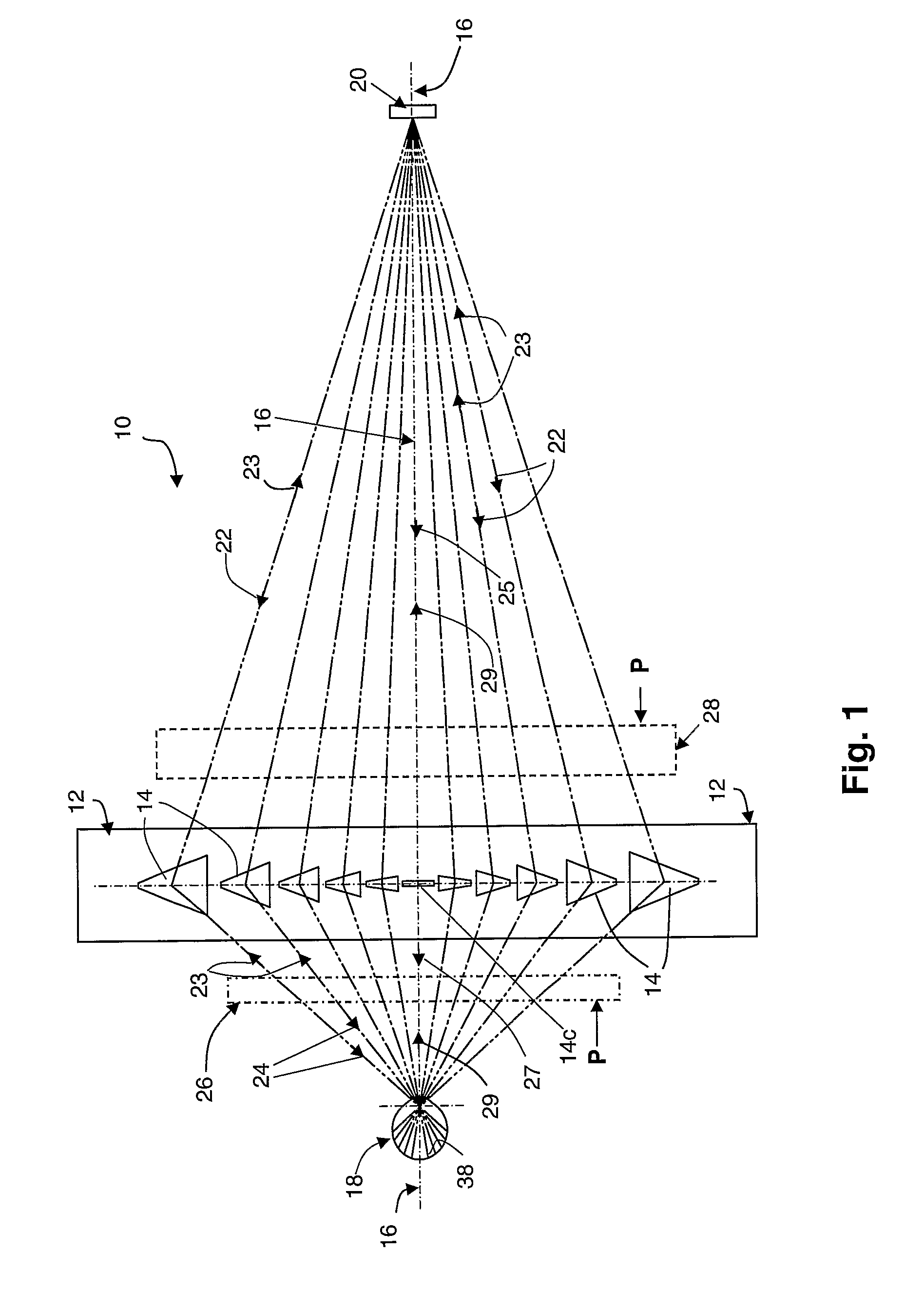
[0031]FIG. 1 is a basic diagrammatic plan of the basic optical layout of the first example of an instrument formed in accordance with the present invention in which the deflector means comprises and array of prisms.

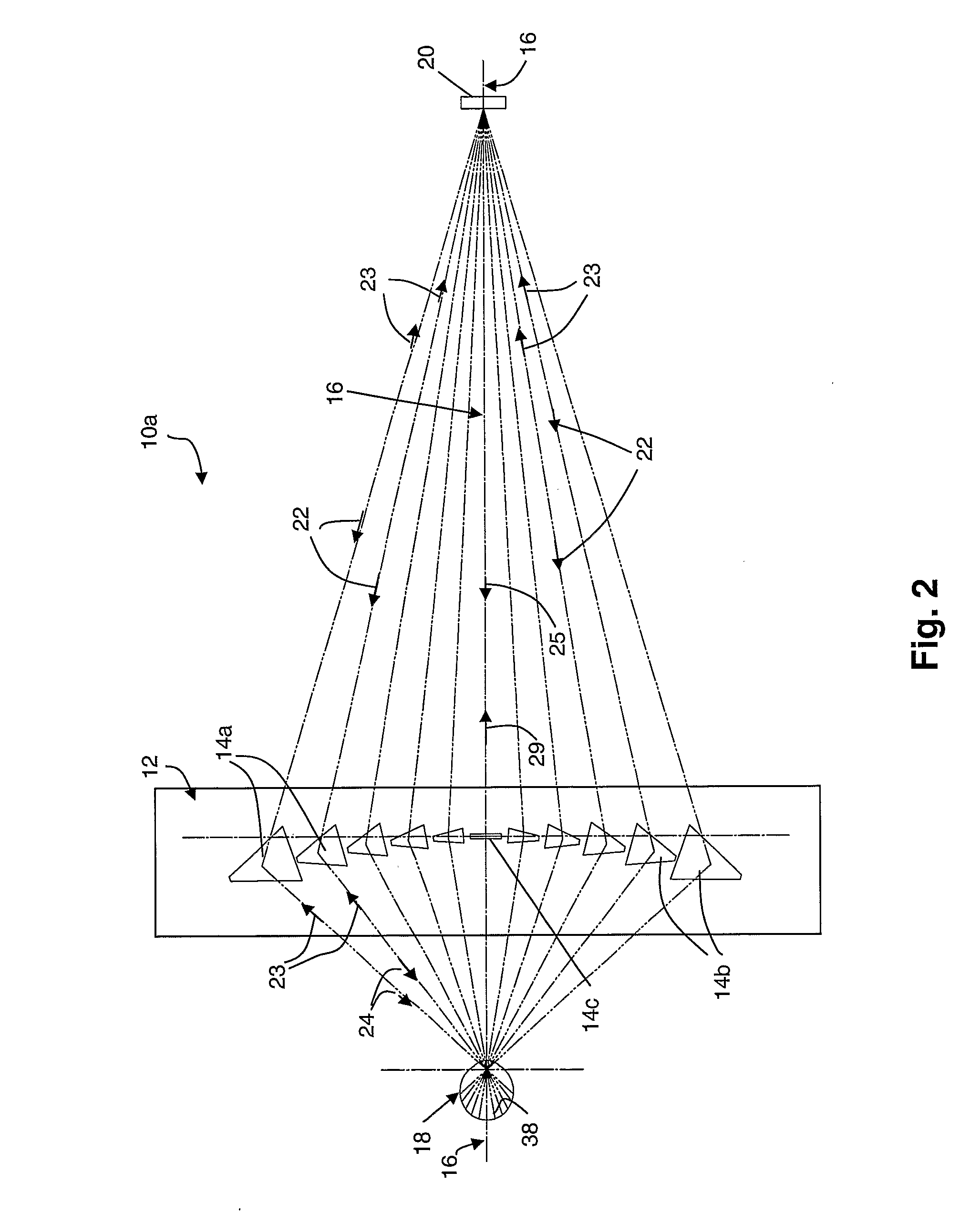
[0032]FIG. 2 illustrates one possible modification to the example of FIG. 1 wherein the prisms comprising the deflector array are tilted and arranged in an arc.

[0033]FIG. 3 is an enlarged and more detailed diagrammatic side elevation of the optical layout of the instrument of FIG. 1.

[0034]FIG. 4 is an enlarged partial detail of FIG. 3 showing some additional to fea...


PUM


Abstract

An instrument and method for characterising eye-related optical systems, including the live human eye involves scanning an illuminating light beam from a light source and light detector unit from element to element of a beam deflector array of elements arranged laterally across the optical axis of eye. At each successive element the illuminating beam is deflected to form an interrogating beam that is directed into the eye at a peripheral angle that depends upon the lateral location of the deflector element. A return beam is reflected or back-scattered from the cornea and returned via the same deflector element to the light source and detector unit. This allows the interrogating beams to be scanned sufficiently rapidly into the eye to greatly reduce the variation of eye fixation and gaze that accompany other methods of measuring peripheral refraction or aberration of a natural eye. In addition to or instead of scanning the illuminating beam over each element of the array, all or multiple elements of the array can be illuminated simultaneously and the multiple interrogating rays thus generated can be gated by the use of an LCD aperture plate. Alternatively, an LCD aperture plate can be interposed between a wide illuminating beam and operated to selectively illuminate the beam deflector

Description

BACKGROUND OF THE INVENTION[0001]1. Technical Field[0002]This invention relates to methods, instruments and apparatus for optically characterising eye-related optical systems, preferably over wide angles of view. Eye-related optical systems include the natural animal eye, alone or in association with prosthetic lenses and with or without surgical or other modification. They also include physical eye models or simulated eyes with or without modification to simulate optical disorders and / or corrective measures.[0003]Optical characterisation typically involves refractometry; that is, the determination of the optical power of portion or the entire optical path traveled by an interrogating ray and it may, for example, include mapping—or spatially resolving—refractive power over an area or surface of the eye-related system, which is sometimes referred to as wavefront aberrometry. Optical characterization may also include determination of the length of the eye-related system, for example t...

Claims


Application Information

Patent Timeline
IPC IPC(8): A61B3/10
CPCA61B3/0008A61B3/1015A61B3/1005A61B3/103
Inventor HO, ARTHURHOLDEN, BRIEN ANTHONYEHRMANN, KLAUS
Owner BRIEN HOLDEN VISION INST (AU)
Why Eureka
Try Eureka