Fan assembly

a technology of fan assembly and rotating blades, which is applied in the direction of motors, liquid fuel engines, non-positive displacement pumps, etc., can solve the problems of uneven or choppy air flow produced by the rotating blades of the fan, general uneven air flow, and uncomfortable for users, so as to reduce carbon debris and emissions, reduce vibration transmission, and widen the range of operating speeds

Active Publication Date: 2010-09-09
DYSON TECH LTD
View PDF105 Cites 140 Cited by
  • Summary
  • Abstract
  • Description
  • Claims
  • Application Information

AI Technical Summary

Benefits of technology

[0022]The base preferably comprises means for generating the air flow. The means for generating the air flow preferably comprises an impeller and a motor for rotating the impeller to create the air flow. The impeller is preferably a mixed flow impeller. Preferably there is a diffuser located within the impeller housing and downstream from the impeller. The motor is preferably a DC brushless motor to avoid frictional losses and carbon debris from the brushes used in a traditional brushed motor. Reducing carbon debris and emissions is advantageous in a clean or pollutant sensitive environment such as a hospital or around those with allergies. While induction motors, which are generally used in fans, also have no brushes, a DC brushless motor can provide a much wider range of operating speeds than an induction motor.
[0023]The base preferably comprises means for inhibiting removal of said means for generating the air flow from the base when the nozzle is detached from the base. The means for inhibiting removal of said means for generating the air flow from the base preferably comprises a retainer located over said means for generating the air flow. The means for generating the air flow preferably comprises a motor located within a motor housing, and wherein said means for inhibiting removal of said means for generating the air flow from the base is preferably arranged to allow movement of the motor housing relative to the base to reduce the transmission of vibrations from the motor housing to the base during use of the fan assembly.

Problems solved by technology

A disadvantage of this type of fan is that the air flow produced by the rotating blades of the fan is generally not uniform.
These variations result in the generation of an uneven or ‘choppy’ air flow which can be felt as a series of pulses of air and which can be uncomfortable for a user.
In addition, this type of fan can be noisy and the noise generated may become intrusive with prolonged use in a domestic environment.
A further disadvantage is that the cooling effect created by the fan diminishes with distance from the user.
The large base body portions, the neck and the one or more air discharging slots limit the arrangement and orientation of components of the fan.
Any inefficiencies in the system, for example losses through the fan housing or disruptions in the air flow path, will reduce the air flow from the fan.
The high efficiency requirement restricts the options for the use of motors and other means for creating air flow.
This type of fan can be noisy as vibrations generated by the motor and impeller and any turbulence in the air flow tend to be transmitted and amplified.

Method used


Image

  • Fan assembly
  • Fan assembly
  • Fan assembly

Examples


Embodiment Construction

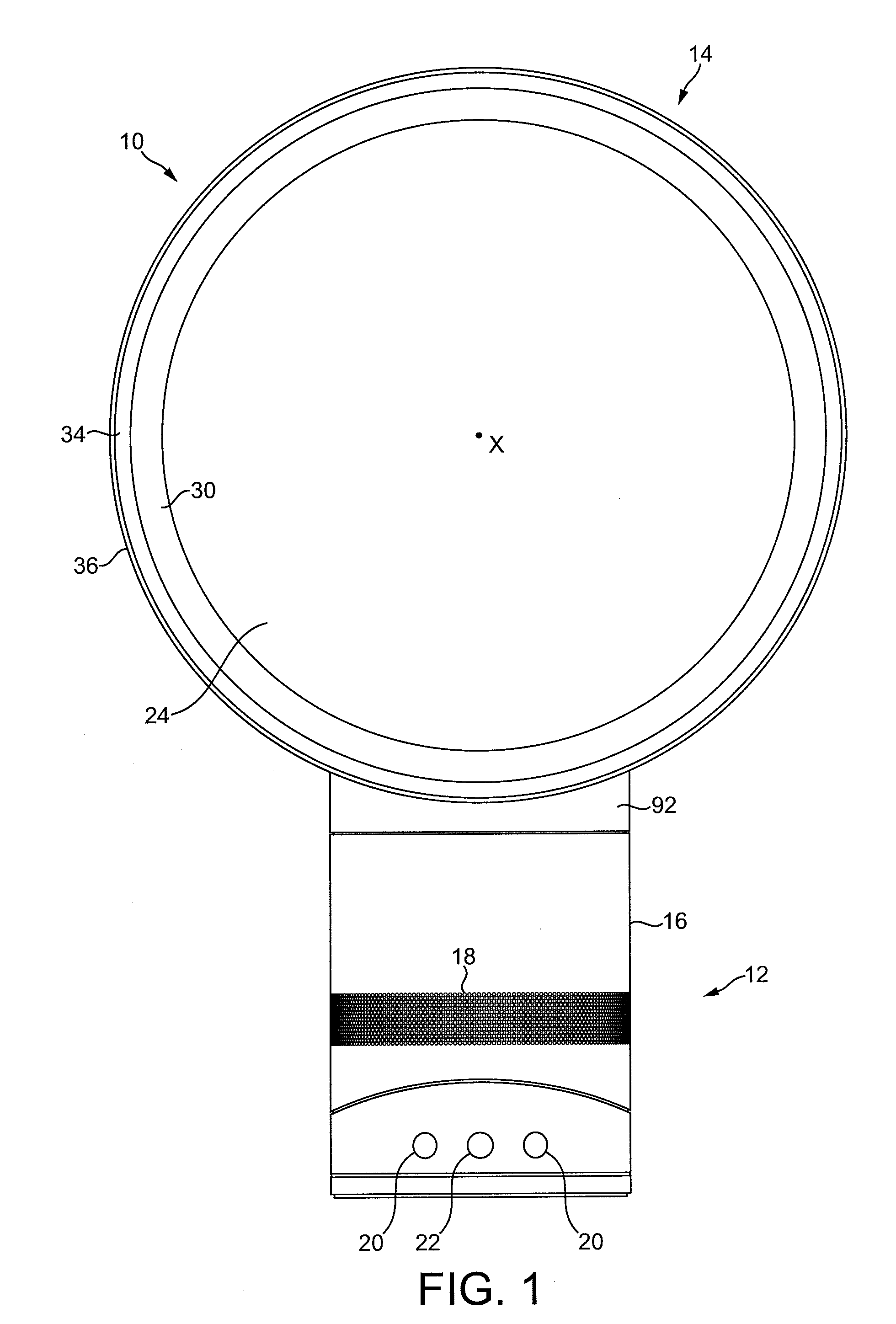
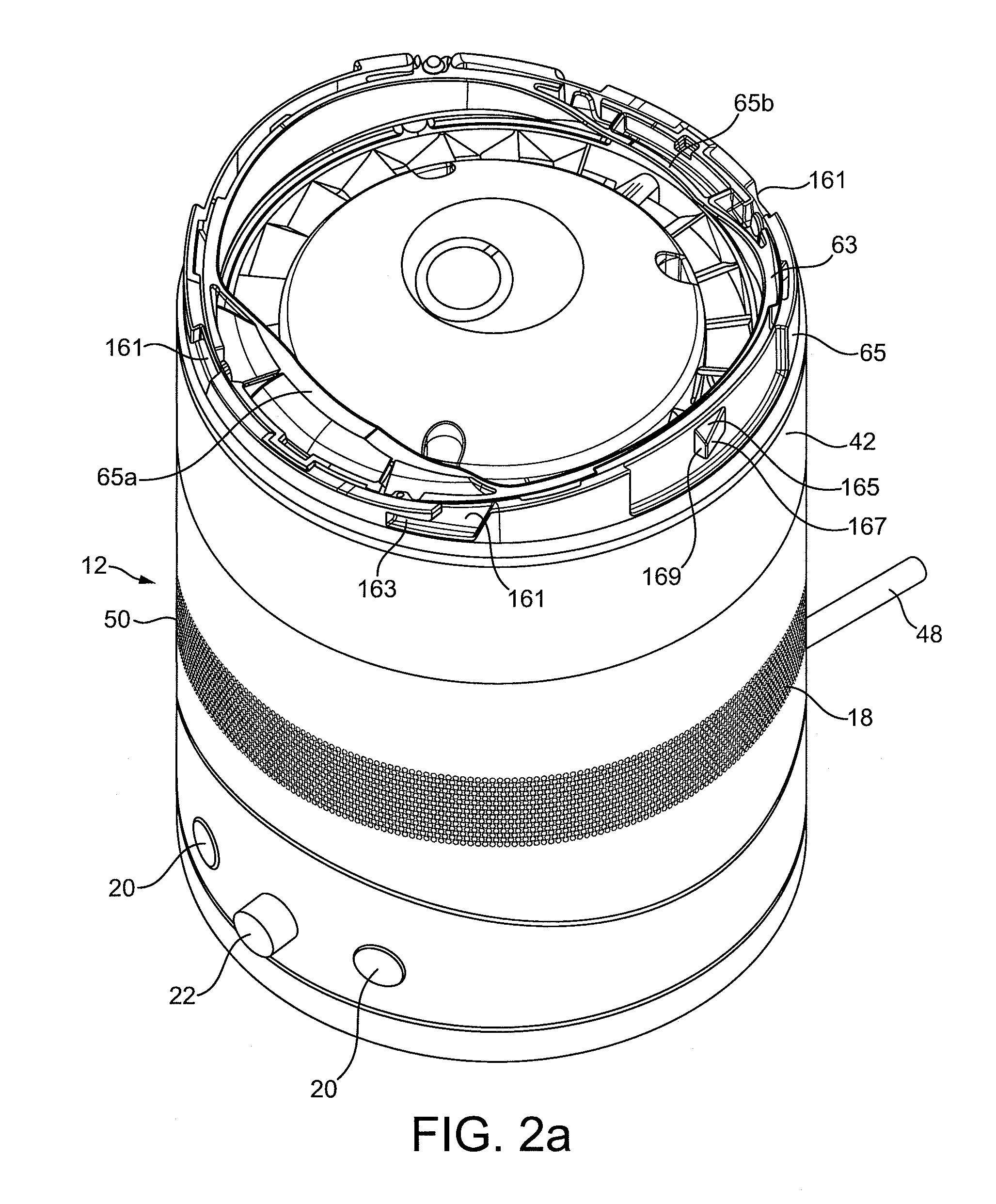
[0048]FIG. 1 is a front view of a fan assembly 10. The fan assembly 10 is preferably in the form of a bladeless fan assembly comprising a base 12 and a nozzle 14 mounted on, detachable from, and supported by the base 12. With reference to FIG. 2(a), the base 12 comprises a substantially cylindrical outer casing 16 having a plurality of air inlets 18 in the form of apertures located in the outer casing 16 and through which a primary air flow is drawn into the base 12 from the external environment. The base 12 further comprises a plurality of user-operable buttons 20 and a user-operable dial 22 for controlling the operation of the fan assembly 10. In this example the base 12 has a height in the range from 200 to 300 mm, and the outer casing 16 has an external diameter in the range from 100 to 200 mm.

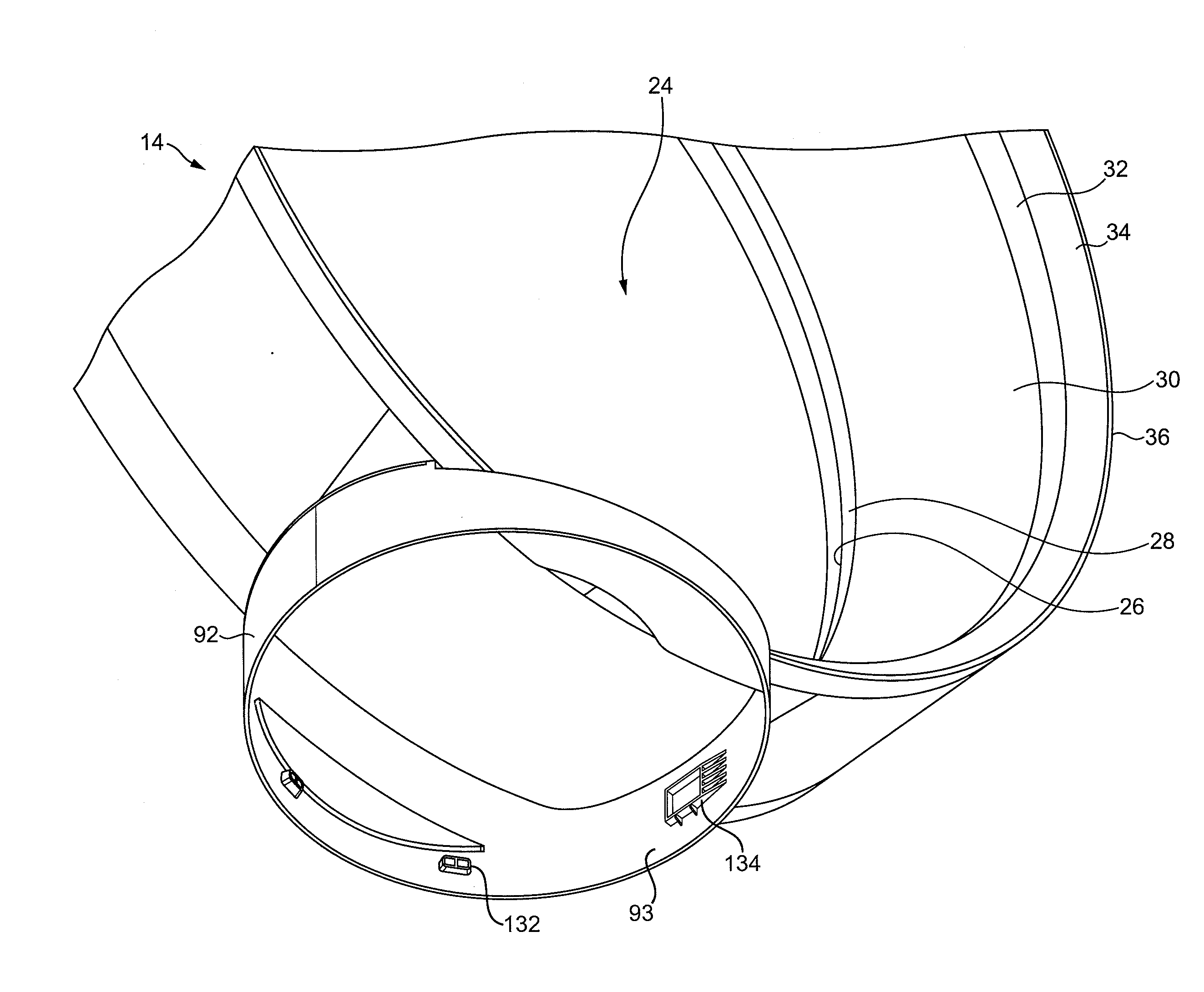
[0049]With reference also to FIG. 2(b), the nozzle 14 has an annular shape and defines a central opening 24. The nozzle 14 has a height in the range from 200 to 400 mm. The nozzle 14 compr...


PUM


Abstract

A bladeless fan assembly for creating an air current includes a nozzle mounted on a base. The nozzle comprises an interior passage and a mouth for receiving the air flow from the interior passage and through which the air flow is emitted from the fan assembly. The nozzle defines an opening through which air from outside the fan assembly is drawn by the air flow emitted from the mouth. The nozzle is detachable from the base, which is preferably sized to be accommodated within the opening of the nozzle for transportation.

Description

REFERENCE TO RELATED APPLICATIONS[0001]This application claims the priority of United Kingdom Application No. 0903665.8, filed 4 Mar. 2009, the entire contents of which are incorporated herein by reference.FIELD OF THE INVENTION[0002]The present invention relates to a fan assembly. Particularly, but not exclusively, the present invention relates to a domestic fan, such as a desk fan, for creating air circulation and air current in a room, in an office or other domestic environment.BACKGROUND OF THE INVENTION[0003]A conventional domestic fan typically includes a set of blades or vanes mounted for rotation about an axis, and drive apparatus for rotating the set of blades to generate an air flow. The movement and circulation of the air flow creates a ‘wind chill’ or breeze and, as a result, the user experiences a cooling effect as heat is dissipated through convection and evaporation.[0004]Such fans are available in a variety of sizes and shapes. For example, a ceiling fan can be at le...

Claims


Application Information

Patent Timeline
Patent Type & Authority Applications(United States)
IPC IPC(8): F01D1/00
CPCF04D25/08F04F5/16F04D29/626F04D29/441F04F5/20F04D29/44F04D29/403
Inventor GAMMACK, PETER DAVIDDYSON, JAMES
Owner DYSON TECH LTD
Why Eureka
Try Eureka