
Method of Molding Composite Material Structural Member and Composite Material Structural Member

Inactive Publication Date: 2010-09-09
MITSUBISHI HEAVY IND LTD
View PDF2 Cites 5 Cited by
  • Summary
  • Abstract
  • Description
  • Claims
  • Application Information

AI Technical Summary

Benefits of technology

[0008]On the other hand, the prepreg does exhibit elasticity in directions that do not coincide with the direction of fiber orientation. In a product prepared by superimposing prepregs with these types of properties so that the direction of fiber orientation differs for each layer, it is desirable to retain elasticity within the required direction, while preventing any reduction in the strength of the final product following autoclaving.
[0024]Furthermore, as described below, when the effect that splitting or inserting partial cuts within the prepreg has on the strength was ascertained using a strength test, it was confirmed that the reduction in strength was significantly less than that caused by fiber creasing. Accordingly, the present invention also has the effect of suppressing any reductions in the strength of the molded product.

Problems solved by technology

However, long stringers and the like with H-shaped or T-shaped cross-sections, which are composite material structural members used during the fabrication of lightweight structures for aircraft and the like, are not only very long, but may also include non-developable surfaces.
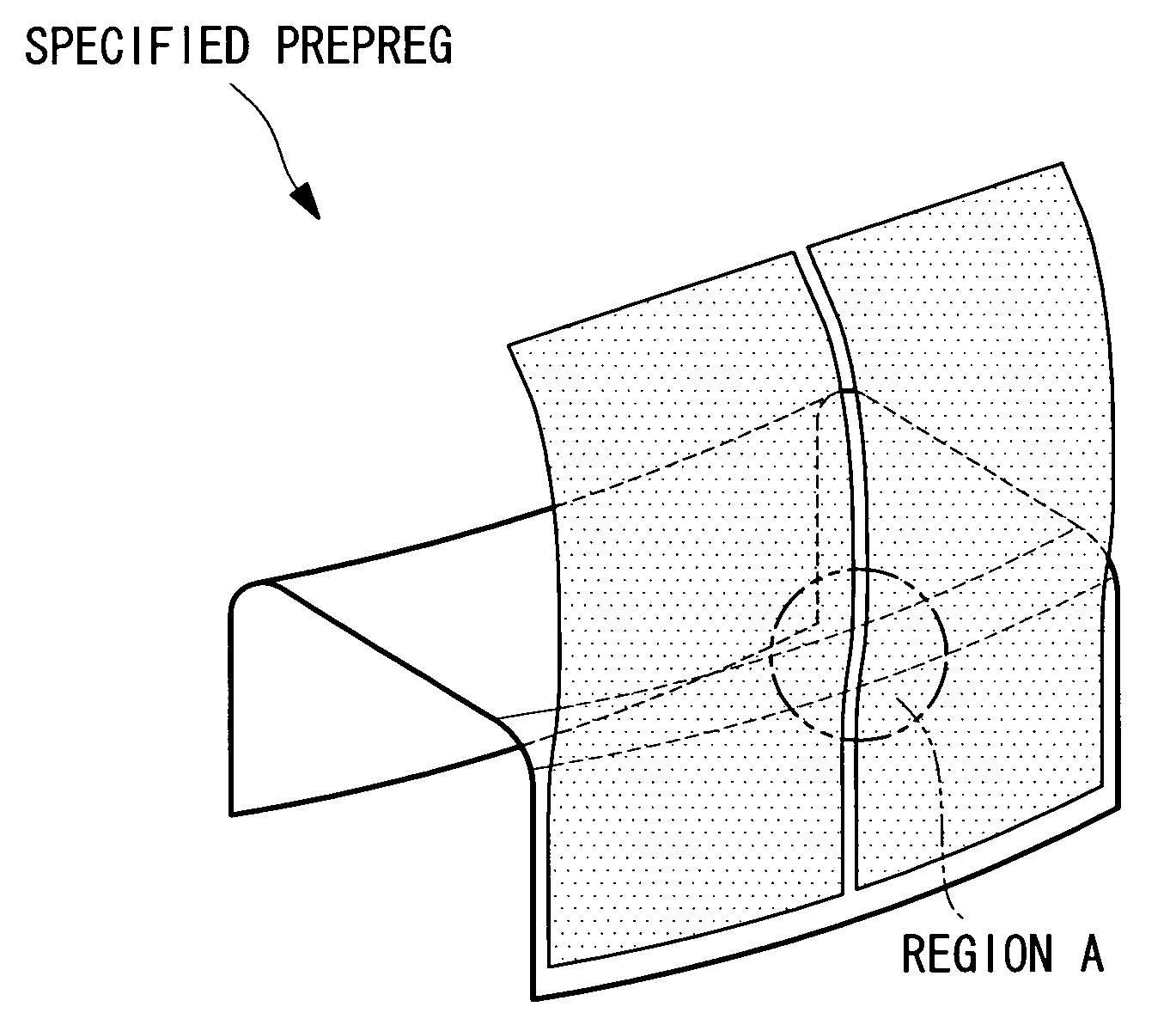
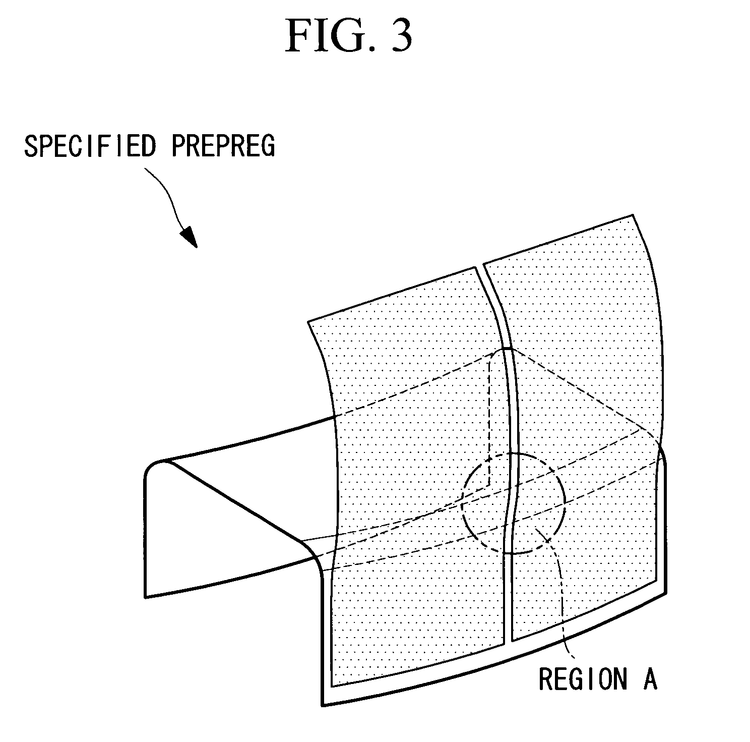
If an attempt is made to prepare a molded item by pressing a flat plate-shaped prepreg laminate against a molding die having this type of non-developable surface, then creasing and cracking may occur, meaning a product of favorable quality cannot be obtained.
The problems described above occur because the fiber used as the reinforcing member within the composite material is a material that exhibits no plastic deformation and has no elasticity.
More specifically, when the prepreg laminate is pressed against the molding die, creases occur in those cases where the length of the fiber is longer than the die shape, whereas cracks occur in those cases where the length of the fiber is shorter than the die shape.

Method used


Image

  • Method of Molding Composite Material Structural Member and Composite Material Structural Member
  • Method of Molding Composite Material Structural Member and Composite Material Structural Member
  • Method of Molding Composite Material Structural Member and Composite Material Structural Member

Examples


Embodiment Construction

[0038]Embodiments of the method of molding a composite material structural member according to the present invention and the resulting composite material structural member are described below based on the drawings.

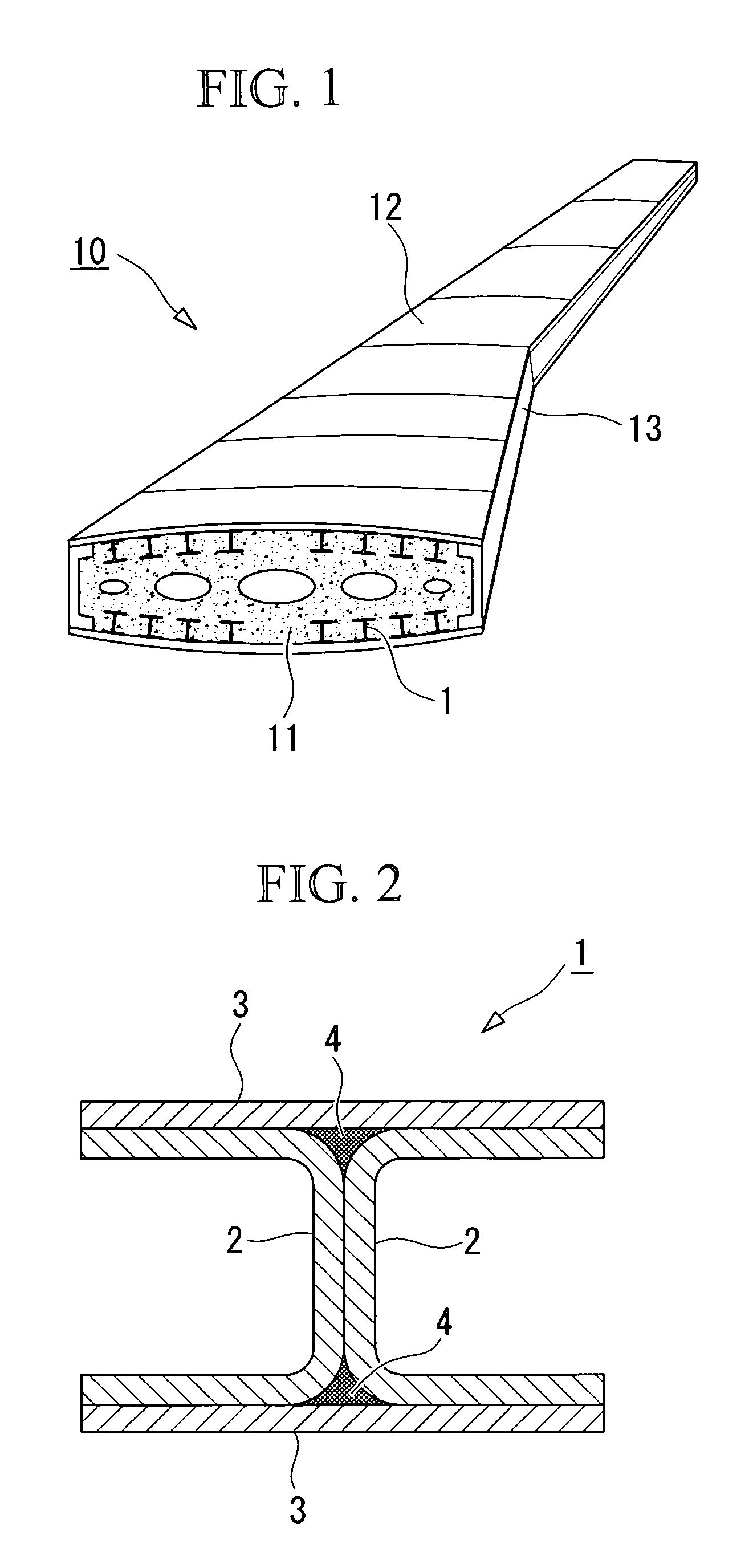
[0039]FIG. 1 is a perspective view showing an example of the structure of a wing box that constitutes a portion of an aircraft main wing. This wing box 10 is a hollow structure in which the backbone is formed by combining a plurality of H-shaped stringers 1 and rib materials 11 in a grid pattern, and the exterior of this backbone is then coated with a skin 12 and spars 13.

[0040]The H-shaped stringers 1 are composite material structural members with an H-shaped cross-section that extend along the length (the longitudinal direction) of the main wing, and are formed, for example, from a carbon fiber composite material comprising carbon fiber combined with a polymer material such as an epoxy resin. As shown in FIG. 2, each of these H-shaped stringers 1 is composed of six compo...


PUM


Abstract

The present invention relates to a method of molding a composite material structural member used mainly within structural members such as channel materials or angle materials, and also to a composite material structural member. An object of the invention is to provide a method of molding a composite material structural member that is capable of suppressing fiber creasing even for very long shapes having non-developable surfaces, and also to provide a composite material structural member.When pressing a prepreg laminate against a molding die, the method comprises a preparation step of preparing a prepreg laminate for molding by laminating a plurality of prepregs with different fiber orientations into a flat plate shape, and a pressure application step of pressing the prepreg laminate for molding prepared in the preparation step against the molding die, and in the preparation step, a specified prepreg having a fiber orientation that coincides with, or is close to, the direction of creasing occurrence is split, either within the region of creasing occurrence or in the vicinity thereof, along a direction that is effective in inhibiting creasing occurrence, and the split prepreg is then used in preparing the prepreg laminate.

Description

TECHNICAL FIELD[0001]The present invention relates to a method of molding a composite material structural member used mainly within structural members such as channel materials or angle materials, and also relates to a composite material structural member.BACKGROUND ART[0002]Conventionally, fiber-reinforced resin composite materials of thermosetting resin composite materials and thermoplastic resin composite materials are used as the structural materials within aircraft, automobiles, ships, and trains and the like. Production of these structural members is performed by preparing a prepreg laminate by laminating layers of the fiber-reinforced resin composite material into a flat plate shape, press molding the prepreg laminate by pressing it against a molding die, and then autoclaving (baking) the molded prepreg laminate.[0003]For example, Japanese Unexamined. Patent Application, Publication No. 2000-271949 (patent citation 1) discloses a technique in which by applying tension continu...

Claims


Application Information

Patent Timeline
IPC IPC(8): B32B5/12B32B37/26
CPCB29C70/222B29C70/34B29C70/342B29D99/0003Y10T156/1067B29L2031/003B29L2031/3076Y10T428/24132B29K2105/246B29C43/02B29C70/06B29K2105/08
Inventor ESAKI, KOUJINONAKA, YOSHINORIMIURA, MASAMINISHIYAMA, SHIGERUABE, TOSHIO
Owner MITSUBISHI HEAVY IND LTD
Learn More