Power Storage Device

a technology of power storage and separator, which is applied in the manufacture of final products, electrode manufacturing processes, climate sustainability, etc., can solve the problems of defective short circuit, easy breakage of separator, and breakage of separator, so as to improve surface area, prevent breakage of separator, and high capacity

Active Publication Date: 2010-09-09
SEMICON ENERGY LAB CO LTD
View PDF15 Cites 41 Cited by
  • Summary
  • Abstract
  • Description
  • Claims
  • Application Information

AI Technical Summary

Benefits of technology

[0005]In order to obtain a power storage device with high capacity, the surface areas of a positive electrode and a negative electrode should be increased. The surface areas of a positive electrode and a negative electrode can be increased by providing a surface of each of the positive electrode and the negative electrode with projections and depressions.
[0008]In addition, if pressure is applied to a separator between a positive electrode and a negative electrode in a thin, small-sized power storage device, the separator may easily be broken.
[0013]Because the surface of each of the positive-electrode active material and the negative-electrode active material is provided with the plurality of projections, the surface area is increased and a thin, small-sized power storage device with high capacity can be obtained.
[0014]Furthermore, because the insulator is provided on each of the plurality of projections, even when pressure is applied between the positive electrode and the negative electrode, the insulator absorbs or disperses the pressure so as to prevent breaking of the separator. Accordingly, a highly reliable power storage device can be obtained.

Problems solved by technology

However, the positive or negative electrode may expand due to charging, and with that pressure, the separator may be broken and defective short circuit may be caused.
In addition, if pressure is applied to a separator between a positive electrode and a negative electrode in a thin, small-sized power storage device, the separator may easily be broken.

Method used


Image

  • Power Storage Device
  • Power Storage Device
  • Power Storage Device

Examples


embodiment 1

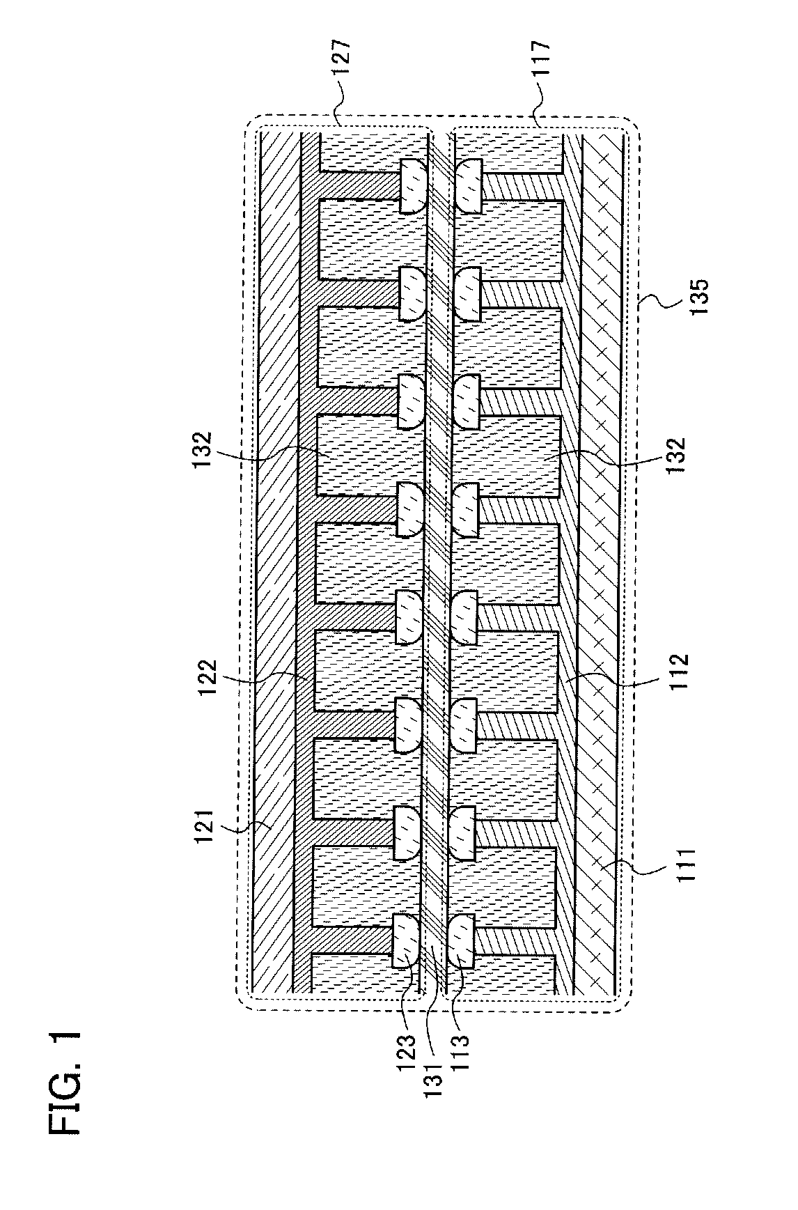
[0020]This embodiment is described with reference to FIG. 1, FIGS. 2A to 2D, FIGS. 3A to 3D, and FIGS. 4A and 4B.

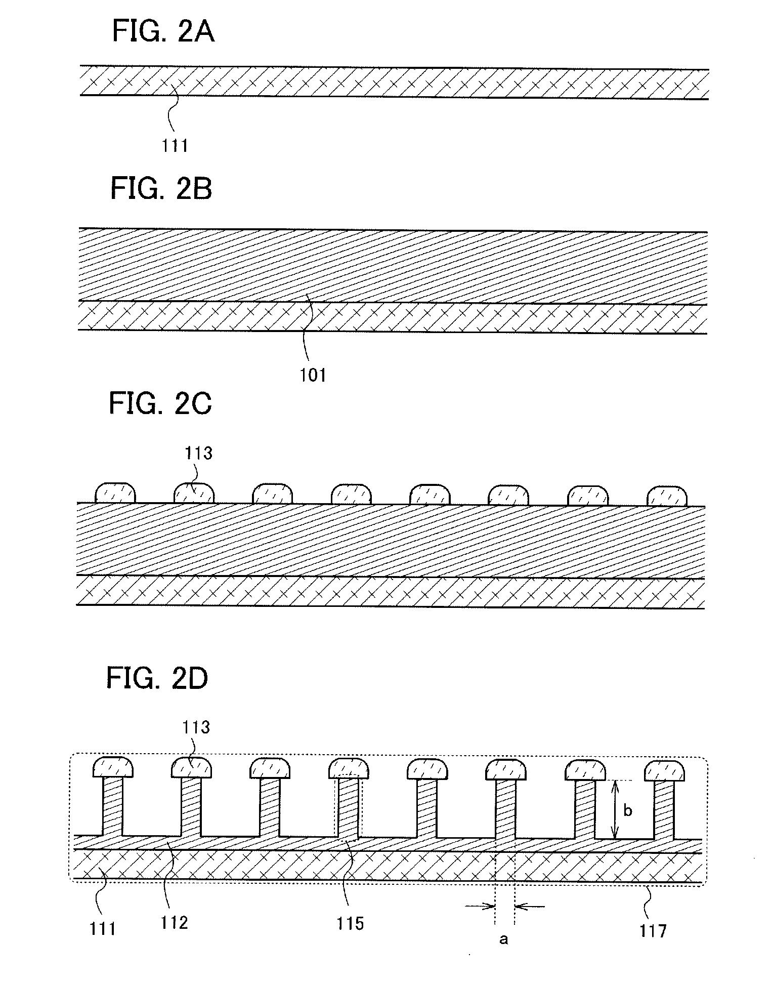
[0021]First, a plate-like positive-electrode current collector 111 is prepared (see FIG. 2A). As the positive-electrode current collector 111, a simple substance, such as aluminum (Al) or titanium (Ti), or a compound thereof may be used.

[0022]Next, a plate-like positive-electrode active material 101 which is a material of a positive-electrode active material 112 is formed over the positive-electrode current collector 111 (see FIG. 2B).

[0023]As the plate-like positive-electrode active material 101, a metal compound (oxide, sulfide, or nitride) having a layered structure can be used. In addition, as the positive-electrode active material 112 for a capacitor, activated carbon can be used. Furthermore, as the positive-electrode active material 112 for a lithium-ion secondary battery where lithium ions are used as carrier ions, a lithium-containing composite oxide represented ...


PUM

PropertyMeasurementUnit
heightaaaaaaaaaa
widthaaaaaaaaaa
widthaaaaaaaaaa

Abstract

The present invention relates to a power storage device including: a positive electrode having a positive-electrode current collector, a positive-electrode active material with a plurality of first projections on the positive-electrode current collector, and a first insulator on an end of each of the plurality of first projections; a negative electrode having a negative-electrode current collector, a negative-electrode active material with a plurality of second projections on a surface of the negative-electrode current collector, and a second insulator on an end of each of the plurality of second projections; a separator between the positive electrode and the negative electrode; and an electrolyte provided in a space between the positive electrode and the negative electrode and containing carrier ions. In each of the first projections and the second projections, a ratio of the height to the width is 3 or more and 1000 or less to 1, i.e. (3 to 1000):1.

Description

BACKGROUND OF THE INVENTION[0001]1. Field of the Invention[0002]The invention disclosed in this specification relates to power storage devices.[0003]2. Description of the Related Art[0004]In recent years, power storage devices, such as lithium-ion secondary batteries, which are power storage devices where carbon or lithium metal oxide is used as a battery material and which are charged and discharged by the movement of lithium ions as carrier ions between a positive electrode and a negative electrode, and electrochemical capacitors, have been actively developed (see References 1 to 3).[References][Reference 1] Japanese Published Patent Application No. 2008-294314[Reference 2] Japanese Published Patent Application No. 2002-289174[Reference 3] Japanese Published Patent Application No. 2007-299580SUMMARY OF THE INVENTION[0005]In order to obtain a power storage device with high capacity, the surface areas of a positive electrode and a negative electrode should be increased. The surface ...

Claims


Application Information

Patent Timeline
Patent Type & Authority Applications(United States)
IPC IPC(8): H01M10/26H01M2/16H01M4/38H01M10/00H01M4/13H01G11/22H01G11/42H01M10/058H01M50/409
CPCH01G11/24Y10T29/49115H01G11/28H01G11/52H01G11/60H01G11/68H01M2/16H01M4/13H01M4/366H01M4/661H01M10/052H01M10/0525H01M10/0566H01M10/0569H01M2004/021H01M2300/0025Y02E60/122Y02E60/13H01G9/038H01G9/02H01G9/016H01G9/058H01G9/155H01G11/26Y02P70/50Y02E60/10C23F4/00H01G11/22H01G11/74H01M4/0404H01M4/139H01M10/058
Inventor YAMAZAKI, SHUNPEIIZUMI, KONAMI
Owner SEMICON ENERGY LAB CO LTD
Why Eureka
Try Eureka