Solar energy module

a solar energy module and solar energy technology, applied in the direction of thermal-pv hybrid energy generation, sustainable manufacturing/processing, lighting and heating apparatus, etc., can solve the problems of reducing the installation cost of the system, reducing the installation cost on site, and reducing the installation cost. , to achieve the effect of reducing the heat loss of the absorbing surface and simple connection of one absorbing surfa

Inactive Publication Date: 2010-09-16
BUCKLEY B SHAWN
View PDF11 Cites 47 Cited by
  • Summary
  • Abstract
  • Description
  • Claims
  • Application Information

AI Technical Summary

Benefits of technology

[0022]Another object of the invention is to construct the module frame using double wall construction that structurally withstands failure to lifetime loads while simultaneously minimizing the materials used in the frame structure.
[0023]Another object of the invention is to construct the module's solar energy absorber component to reduce heat loss from absorbing surfaces, to protect fragile internal components, to structurally withstand failure under lifetime loads while simultaneously minimizing the materials used in the absorber structure and to allow for simple connection of one absorber to another during field installation.

Problems solved by technology

The other component is the cost of the system's installation.
Since on-site installation can be as costly as the system cost, reducing on-site installation costs leads to a lower installed cost and faster payback period.
It is called “waste heat” because the heat is often dumped to the atmosphere and wasted.
That means 80% of the available solar flux is wasted unless it can be used locally.

Method used


Image

  • Solar energy module
  • Solar energy module
  • Solar energy module

Examples


Embodiment Construction

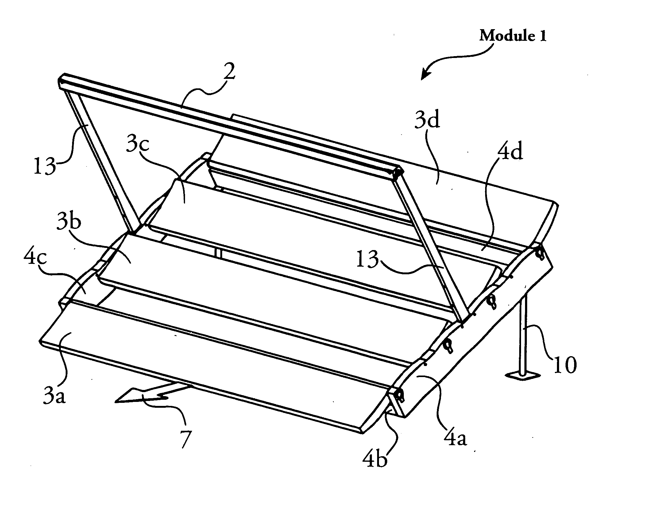
[0044]In the following, each member of a set of similar components will have a suffix letter (a, b, c, d . . . ) to distinguish each individual member of the set. For example, reflectors 3 refer to the set of reflectors 3a, 3b, 3c, and 3d. Another annotation uses ellipses (a series of dots) between the set's first element and the set's last element to describe a set, i.e., reflectors 3 can also be referred to as 3a . . . 3d.

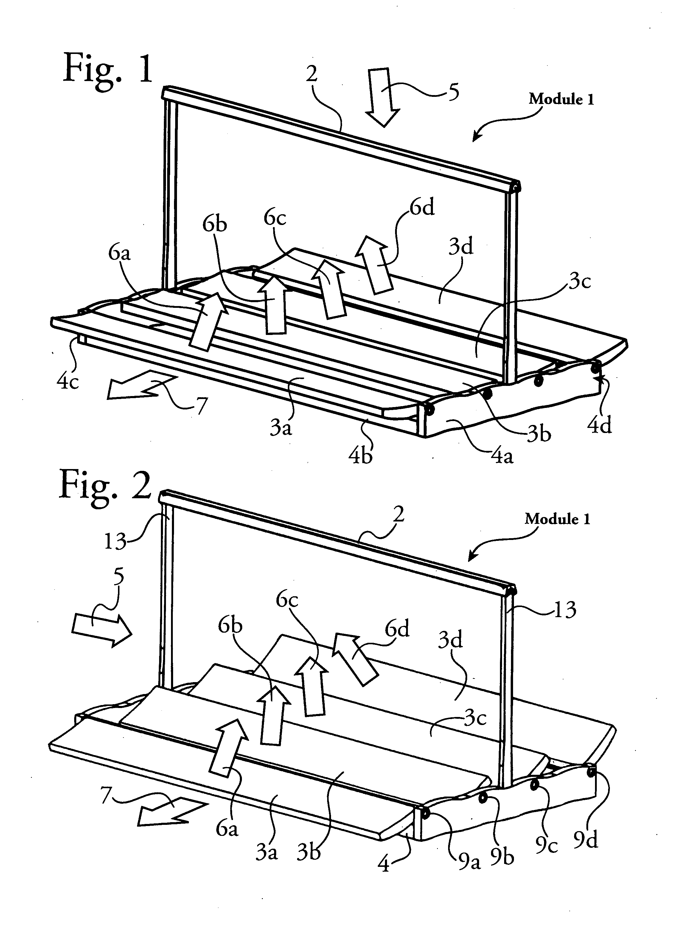
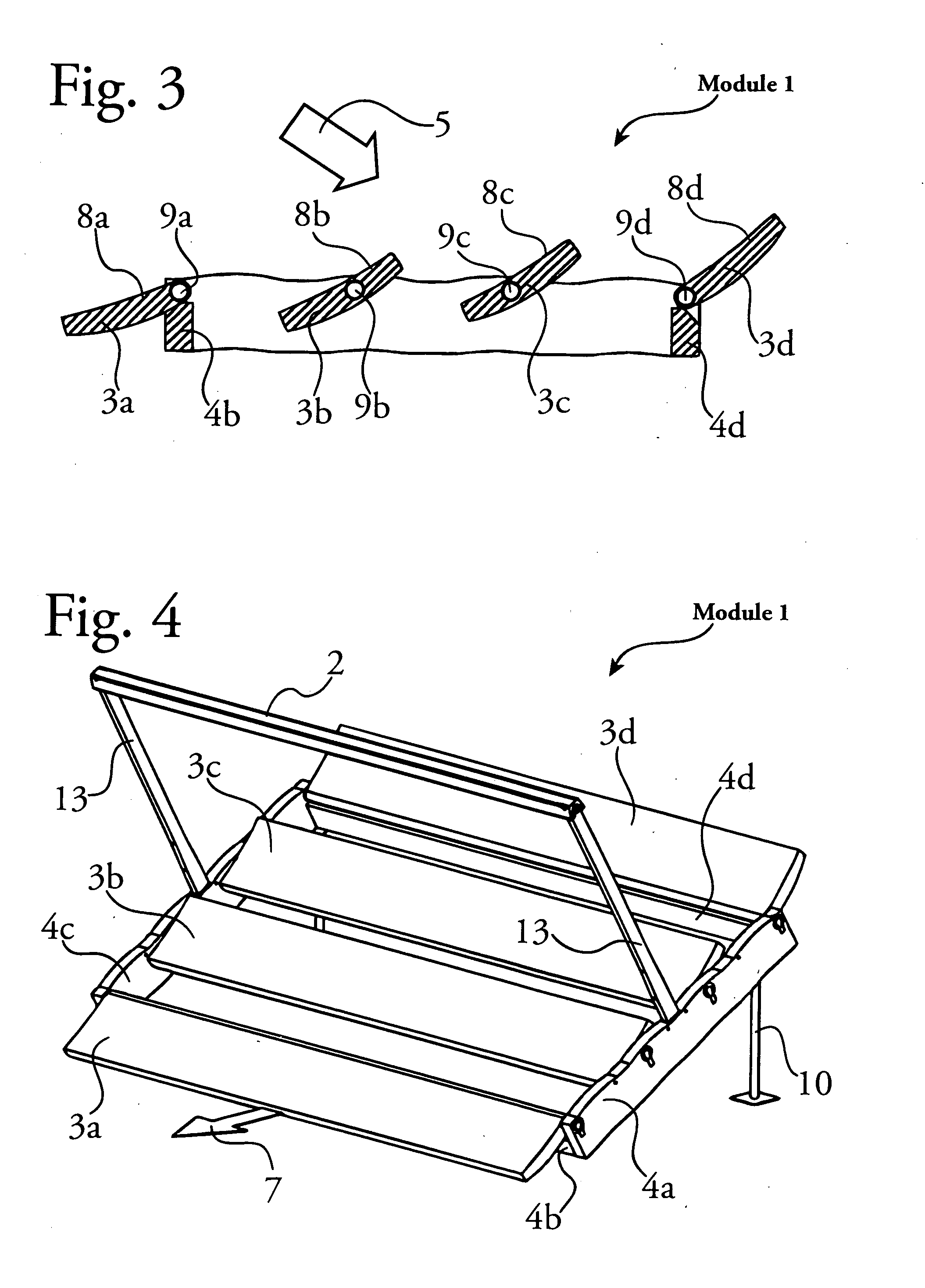
[0045]FIG. 1 shows the preferred embodiment of module 1 during normal usage absorbing solar energy from the sun. The sun's energy is shown diagrammatically as the arrow 5 directing solar energy onto the module 1. Solar energy is reflected from reflectors 3a . . . 3d onto absorber 2 where it heats a fluid flowing through absorber 2 or generates electricity by photovoltaic devices within absorber 2.

[0046]Each of reflectors 3a . . . 3d reflect some portion of the solar energy 5 directed on a reflector 3 to the absorber 2. Each reflector 3a . . . 3d redirects solar ...


PUM


Abstract

A low cost mass-produced solar module that extracts both electricity and heat from the sun. One or more reflectors held by a frame reflect the sun's heat into an absorber. Each reflector rotates about its axle to keep its reflected solar energy focused on the absorber. In one embodiment, solar heat is focused to heat fluid that flows to thermodynamic engines that convert the heat to electricity. Engine waste heat is also captured for use as building heat, home hot water or industrial process heat. In another embodiment, solar heat is focused onto photovoltaic devices that directly convert light into electricity. The fluid that cools the photovoltaic devices can be used for building heat, home hot water or industrial process heat. The frame shields the reflectors from ambient wind loads, supports reflector axles accurately and simplifies installation on roofs or walls of buildings. The frame, reflectors, absorber and ancillary components comprise a module that can be shipped, installed and operated by low skill. Most components are fabricated using “double wall” construction formed by two face sheets held apart by a core that reduces their weight and their cost. Reflector surfaces are curved to focus the sun and to provide additional strength. Module design includes methods to install, maintain and verify proper functioning of the modules. In addition, methods show how electrical energy can be derived from the module, both circulating fluids that power thermodynamic engines and by photovoltaic cells that are cooled by the circulating fluid. Sensors contained in the modules detect aberrant behavior and optimize reflector trajectories to extract the most solar heat available. Communication between modules allows optimization of an array of modules.

Description

FIELD OF THE INVENTION[0001]This invention relates to energy production, in particular, a low-cost mass-produced solar module that extracts both electricity and heat from the sun.BACKGROUND OF THE INVENTION[0002]Solar energy becomes an alternative to burning fossil fuels when the installed cost of the solar energy harvesting system is low and the value of the captured energy is high. Payback period is a simple way of judging the economics of alternative energy systems. The payback period is the installed cost of the system divided by its yearly energy savings; its units are usually in years.[0003]The installed cost is composed of two components. One is the system cost, the sum of all the components of the system itself. The system cost is kept low by fabricating a system from low-cost materials and by reducing the weight of these materials to the minimum while still resisting structural loads that are experienced during its lifetime. The other component is the cost of the system's i...

Claims


Application Information

Patent Timeline
Patent Type & Authority Applications(United States)
IPC IPC(8): F24J2/50F24J2/10F24S10/40F24S20/20F24S23/70F24S50/20
CPCF24J2/055H01L31/0547F24J2/10F24J2/1057F24J2/38F24J2/40F24J2/4636F24J2/4638F24J2/52F24J2/541F24J2002/108F24J2002/5482Y02B10/12Y02B10/22Y02E10/41Y02E10/44Y02E10/47Y02E10/52F24J2/4623Y02E10/60Y02B10/70H02S20/00H02S40/44F24J2002/5468H01L31/0422H01L31/0522H01L31/058F24J2/07F24S10/45F24S20/20F24S23/70F24S23/82F24S25/00F24S30/425F24S40/52F24S40/80F24S40/85F24S50/00F24S50/20F24S2023/872F24S2030/136F24S2030/15H02S20/22H02S20/23H02S20/30H02S20/32H02S40/425H01L31/054Y02B10/10Y02B10/20Y02E10/46Y02P80/20Y02E10/40
Inventor BUCKLEY, B. SHAWN
Owner BUCKLEY B SHAWN
Why Eureka
Try Eureka