Machinery arrangement of a marine vessel
- Summary
- Abstract
- Description
- Claims
- Application Information
AI Technical Summary
Benefits of technology
Problems solved by technology
Method used
Image

Examples
second embodiment
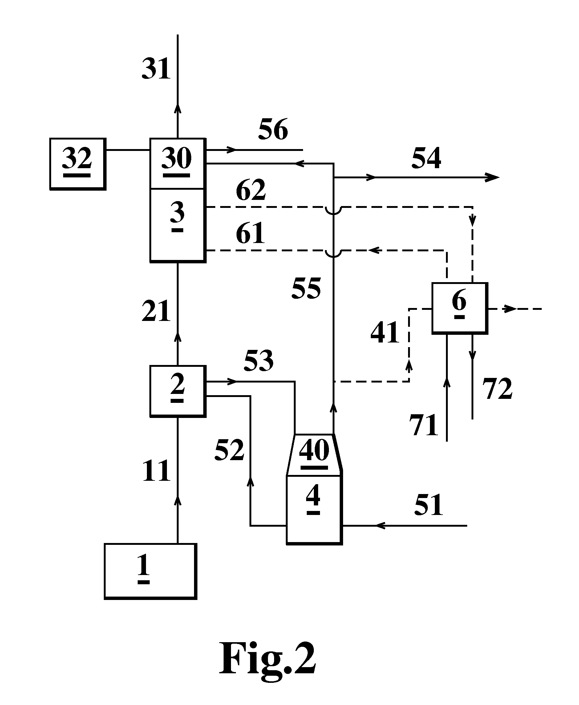
[0029]FIG. 2 shows the present invention, more or less similar to the arrangement as discussed above in connection with FIG. 1. The same reference numerals are used for the corresponding components. This embodiment, however, includes a dumping device 6 normally used on marine vessels for dumping excess heat as discussed above.
[0030]In conventional arrangements, the dumping device 6 would have been connected to the separate heating system 4 for dumping excess heat from the heat recovery device 2 via the steam drum 40 of the heating system 4 as indicated by dotted flow line 41.
[0031]In this case, however, according to the invention, the conventional dumping device available on board has been connected to the scrubber unit 3 for assisting in the scrubbing process. Scrubbing of exhaust gases is normally done by circulating a scrubbing medium, e.g. water, through the exhaust gas flow. The broken flow lines 61 and 62 indicate the circulation of the scrubbing medium from the dumping device...
third embodiment
[0033]FIG. 3 shows the present invention, more or less similar to the arrangement as discussed above in connection with FIG. 1. The same reference numerals are used for the corresponding components.
[0034]This embodiment includes an extended heat recovery section 8 arranged at the exhaust gas inflow end of the scrubber unit 3. The water and steam mixture generated in the heat recovery device 2 may subsequently be circulated, as indicated by flow line 81 and flow line 82, through the (still hot) exhaust gas flow in the additional heat recovery section 8 at the inflow end of the scrubber unit 3 in order to recover low grade heat, which then may be circulated through the steam drum 40 of the separate heating system 4 and further to the reheating device 30 of the scrubber unit 3.
[0035]This arrangement maximises the recovery of waste heat generated by the machinery arrangement of the marine vessel. It also ensures that there is heat available for the reheating device 30 of the scrubber un...
fourth embodiment
[0036]FIG. 4 shows the present invention, more or less similar to the arrangement as discussed above in connection with FIG. 1. The same reference numerals are used for the corresponding components.
[0037]In this embodiment a feed water flow line 511 (an extension of the primary feed water flow line 51) is led past the separate heating system 4 and combined with flow line 521, which is a branch off line from the circulating water flow line 52 leading to the waste heat recovery device 2. Flow lines 511 and 521 are combined into flow line 811. The combined flow, flow line 811, consequently has a higher temperature than the primary feed water (flow line 51). This combined flow is led to and circulated through an extended waste heat recovery section 8 arranged at the exhaust gas inflow end of the scrubber unit 3.
[0038]As the heated combined flow circulates through the extended heat recovery section 8, it can capture energy from the low grade waste heat at the exhaust gas inflow end of th...
PUM
 Abstract
Description
Claims
Application Information
 - R&D
- Intellectual Property
- Life Sciences
- Materials
- Tech Scout
- Unparalleled Data Quality
- Higher Quality Content
- 60% Fewer Hallucinations
Browse by: Latest US Patents, China's latest patents, Technical Efficacy Thesaurus, Application Domain, Technology Topic, Popular Technical Reports.
© 2025 PatSnap. All rights reserved.Legal|Privacy policy|Modern Slavery Act Transparency Statement|Sitemap|About US| Contact US: help@patsnap.com