Coil manufacturing method and coil manufacturing apparatus

US20100231083A1Inactive Publication Date: 2010-09-16AISIN AW CO LTD

Image

  • Coil manufacturing method and coil manufacturing apparatus
  • Coil manufacturing method and coil manufacturing apparatus
  • Coil manufacturing method and coil manufacturing apparatus

Examples


Embodiment Construction

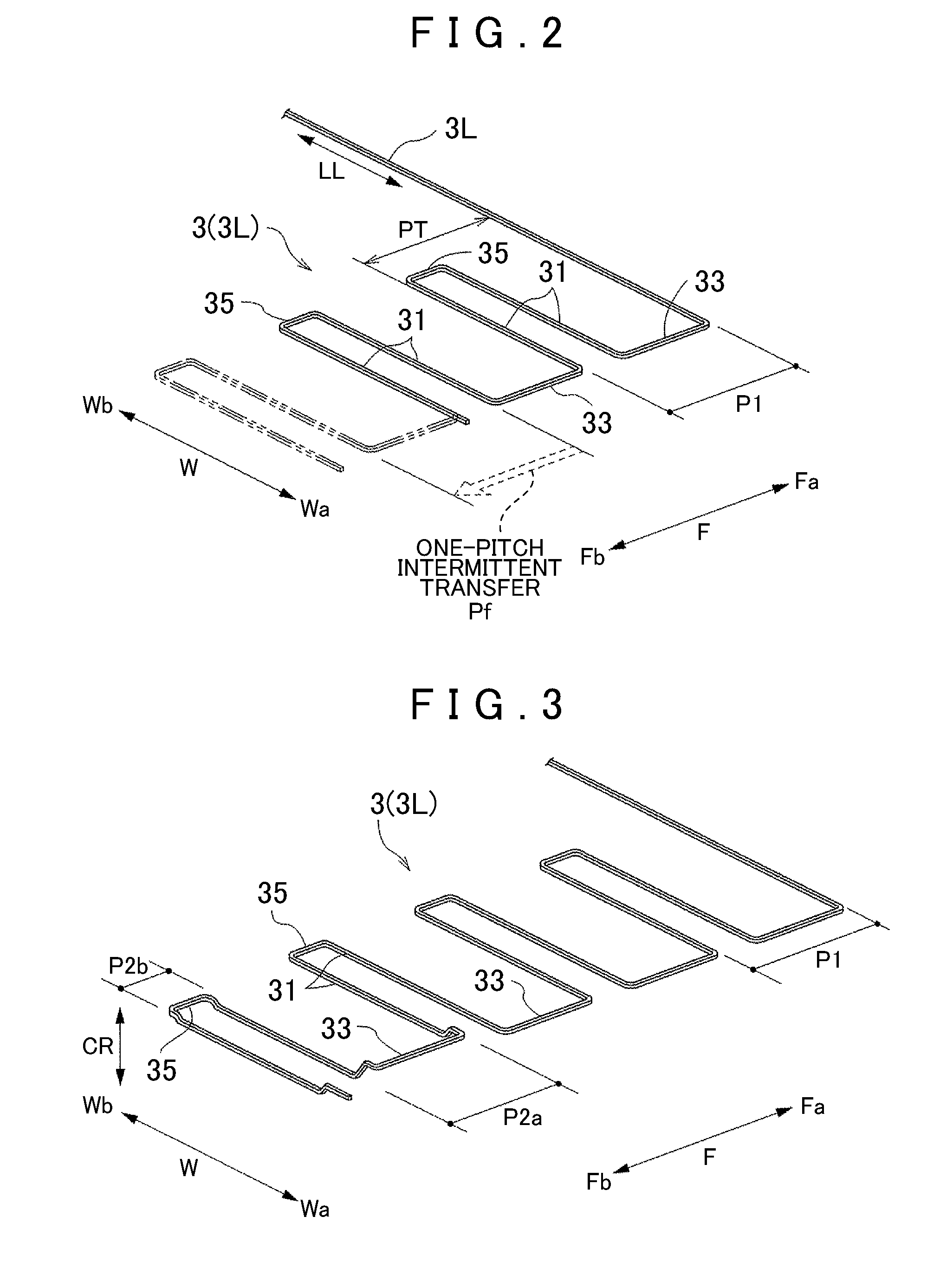
[0082]A coil manufacturing method and a coil manufacturing apparatus 1 (see FIG. 13) and a wave wound coil 3C (see FIG. 11) that is a coil manufactured by the method and the apparatus according to an embodiment of the present invention will be described based on the drawings. The coil manufacturing method and the coil manufacturing apparatus 1 are the method and the apparatus for manufacturing a substantially cylindrical wave wound coil 3C by shaping a linear conductor 3L with a cross-sectional shape having directionality (see FIG. 2). In this embodiment, one sequential linear conductor 3L is shaped from one end side sequentially to produce a substantially cylindrical wave wound coil 3C. Such a substantially cylindrical wave wound coil 3C is preferably used as, for example, an armature coil for rotary electrical machine. Here, the “rotary electrical machine” is used as a concept including all of a motor (electric motor), a generator (power generator), and a motor-generator which ser...


PUM

PropertyMeasurementUnit
Lengthaaaaaaaaaa
Shapeaaaaaaaaaa
Widthaaaaaaaaaa

Abstract

A coil manufacturing method for manufacturing a wave wound coil in a substantially cylindrical shape by shaping a linear conductor with a cross-sectional shape having directionality, including: transferring a linear waver conductor shaped in a substantially rectangular waveform, and having straight side portions extending in a wave width direction, one-side connecting portions sequentially connecting every other pair of adjacent side portions at ends on a one wave width direction side, and other-side connecting portions sequentially connecting pairs of adjacent side portions that are not connected by the one-side connecting portions at ends on an other wave width direction side; bending a target connecting portion, which is at least one of the one-side connecting portions and the other-side connecting portions of the wave conductor, at one position thereof to shape the target connecting portion into a substantially V shape so that the side portions are arranged along a coil circumferential direction and directions of cross-sectional shapes of the side portions are in a constant direction with respect to a coil radial direction; and winding the bent wave conductor on a bobbin.

Description

[0001]The disclosure of Japanese Patent Application No. 2009-061745 filed on Mar. 13, 2009 including the specification, drawings and abstract is incorporated herein by reference in its entirety.BACKGROUND OF THE INVENTION[0002]The present invention relates to a coil manufacturing method and a coil manufacturing apparatus for manufacturing a substantially cylindrical wave wound coil by shaping a linear conductor with a cross-sectional shape having directionality, and to a coil manufactured by the method and the apparatus.DESCRIPTION OF THE RELATED ART[0003]Regarding a coil manufacturing method for manufacturing a substantially cylindrical wave wound coil, a technique is known in which a wave wound coil is shaped by bundling up a plurality of windings of a linear conductor with a circular cross section having no directionality in a ring shape, bending the windings of the linear conductor to make a predetermined star-shaped winding unit, and shaping this star-shaped winding unit into a...

Claims


Application Information

Patent Timeline
16 Sep 2010
Publication
US20100231083A1
IPC
H02K23/32; H02K15/04; B23P19/00
CPC
H01F41/06; Y10T29/49009; Y10T29/53161; H02K15/0478
Inventors
HASHIMOTO, SHINGO; SAITO, MASAKI