Electronic device for self oscillating class d system

a self-oscillating, electronic device technology, applied in amplifiers, amplifiers with semiconductor devices/discharge tubes, amplifiers, etc., can solve the problems of severe interference of circuitry functionality, undesired offset of electronic components, etc., to avoid additional disturbance of duty cycles, smooth start-up, and without undesired audible effects

Inactive Publication Date: 2010-09-16
NXP BV
View PDF4 Cites 10 Cited by
  • Summary
  • Abstract
  • Description
  • Claims
  • Application Information

AI Technical Summary

Benefits of technology

[0013]The present invention also suggests to apply at least one well defined DC offset to the modulation stage. During the start-up procedure, a small unbalance is introduced into the comparator in order to set the comparator's output to low. Consequently, the output of the power stage is also tied to LOW level during the start-up procedure. This mechanism provides enough time to have the boot capacitor charged to a sufficiently higher voltage level. The unbalance by a predefined DC offset of the comparator is only applied during a very short period of time, as for example during 1 μsec. The signal applied to the comparator is derived from a dedicated logical circuitry providing a time period of a sufficiently short value. The offset which is externally applied to the comparator is determined based on the maximum DC offset caused by process parameter variations. The general behavior of the comparator remains unchanged, except that the first switching cycle of the output power stage is forced to LOW level. The natural frequency of the self-oscillating class D system is not affected by the principle according to the present invention. Even during the first cycles when the loop starts switching, the natural frequency will be preserved avoiding additional disturbances of the duty cycles. Further, the principle according to the present invention provides a smooth start-up behavior without undesired audible effects. It should also be noticed, that the electronic device according to present invention, or parts of the electronic device, are preferably implemented as integrated circuits.
[0014]The object of the present invention is further solved by a method of designing an electronic device. The method includes the steps of providing a compensation circuit for a modulation stage of an integrated power comparator circuit for a self-oscillating class D system. According to this aspect of the invention, the compensation circuit is also adapted to provide a compensation signal to the modulation stage, wherein the compensation signal is dimensioned for compensating an effect of a variation of a production parameter for smoothing initialization of the self-oscillating class D system.
[0015]Still further, the object of the present invention is solved by a method of operating a class D system. The method includes the steps of providing a compensation signal to a modulation stage for an integrated power comparator circuit for a self-oscillating class D system, wherein the compensation signal is dimensioned for compensating an effect of a variation of a production parameter for smoothing initialization of the self-oscillating class D system. Preferably, the modulation stage has a comparator, and the offset compensation signal provides a pulse for compensating or over-compensating an offset of the comparator being the effect of the variation of the production parameter.

Problems solved by technology

In particular, if two components are supposed to have the same electrical properties, i.e. they should match, process variations can impair the functionality of the circuitry severely.
One effect of process variations during manufacturing is an undesired offset of the electronic components, such an offset of a comparator, or the differential pair of a comparator, etc.

Method used


Image

  • Electronic device for self oscillating class d system
  • Electronic device for self oscillating class d system
  • Electronic device for self oscillating class d system

Examples


first embodiment

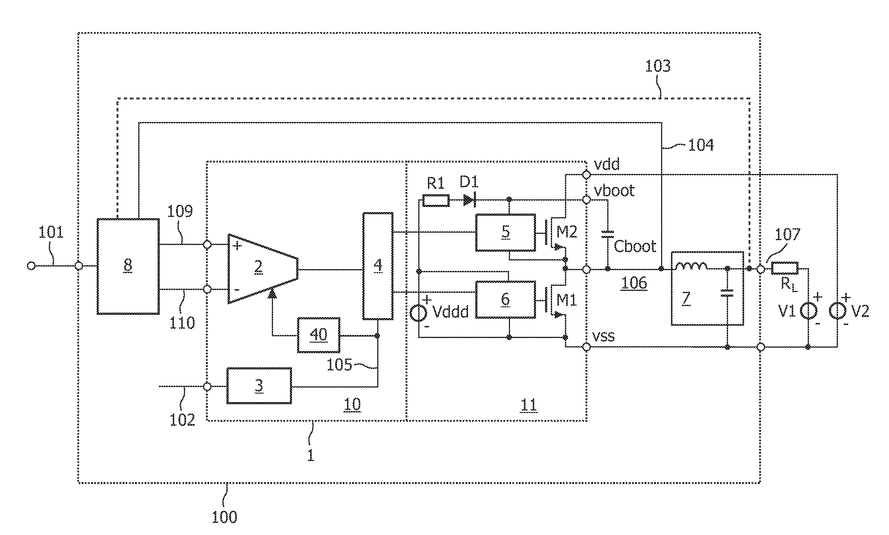
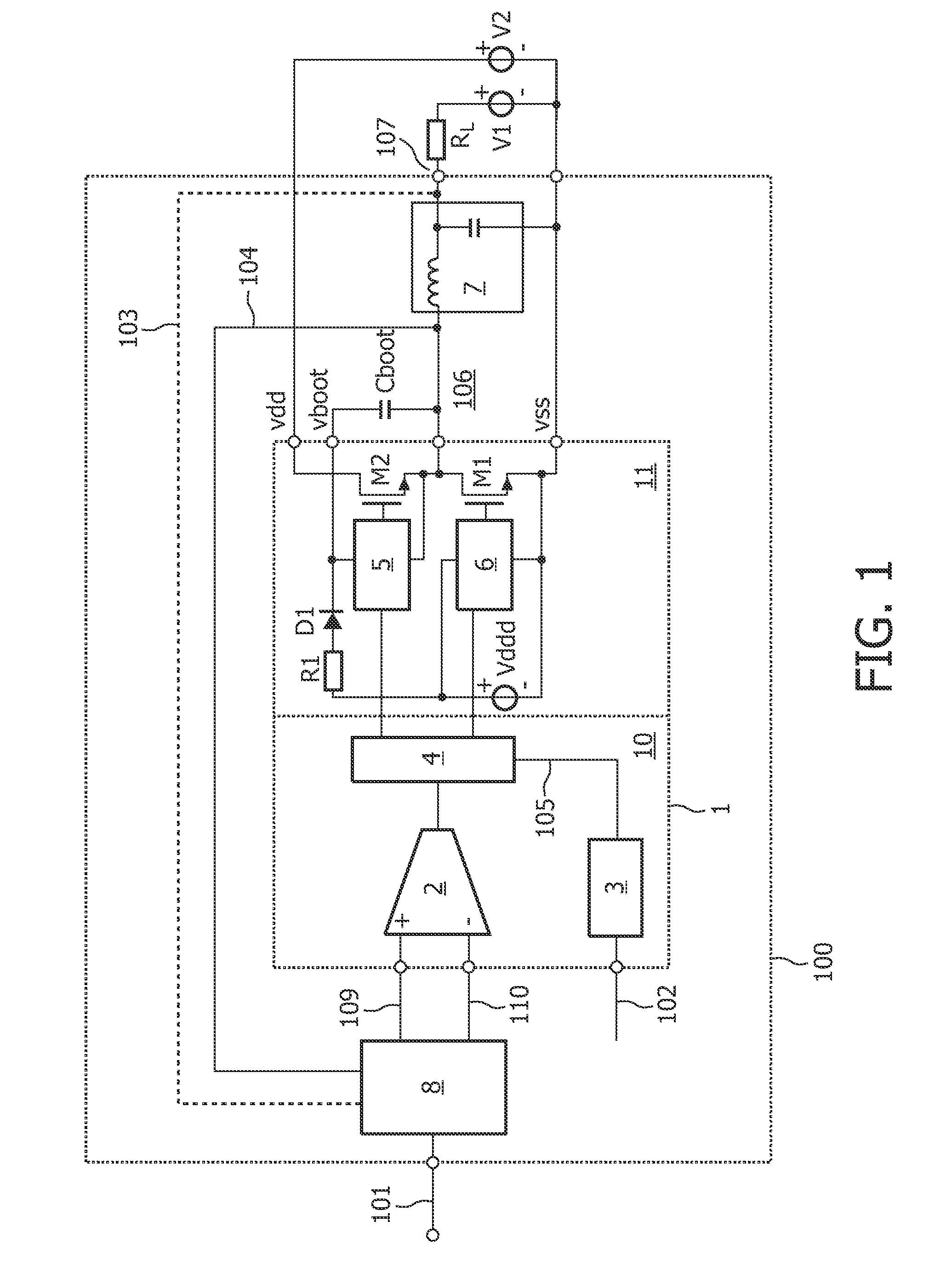
[0023]FIG. 1 shows a simplified block diagram of a self-oscillating class D system according to the prior art. The self-oscillating class D system 100 includes an integrated circuit usually designated as an integrated power comparator 1.

[0024]The integrated power comparator 1 has substantially the same behavior as a comparator, except that the output signal 106 of the integrated power comparator 1 is modulated and rapidly switched between Vdd and Vss (ground) in accordance with an audio input signal 101. The supply voltage Vdd is provided by voltage source V2. The rapid switching between supply lines Vdd and Vss enables the integrated power comparator 1 to provide a current of several amperes on the output pin 106. The output signal on node 106 is typically modulated by pulse width modulation (PWM).

[0025]The self-oscillating class D system 100 of FIG. 1 is configured as a closed loop. Therefore, the class D system 100 further includes a discrete loop filter 8 as shown in FIG. 1. The...

second embodiment

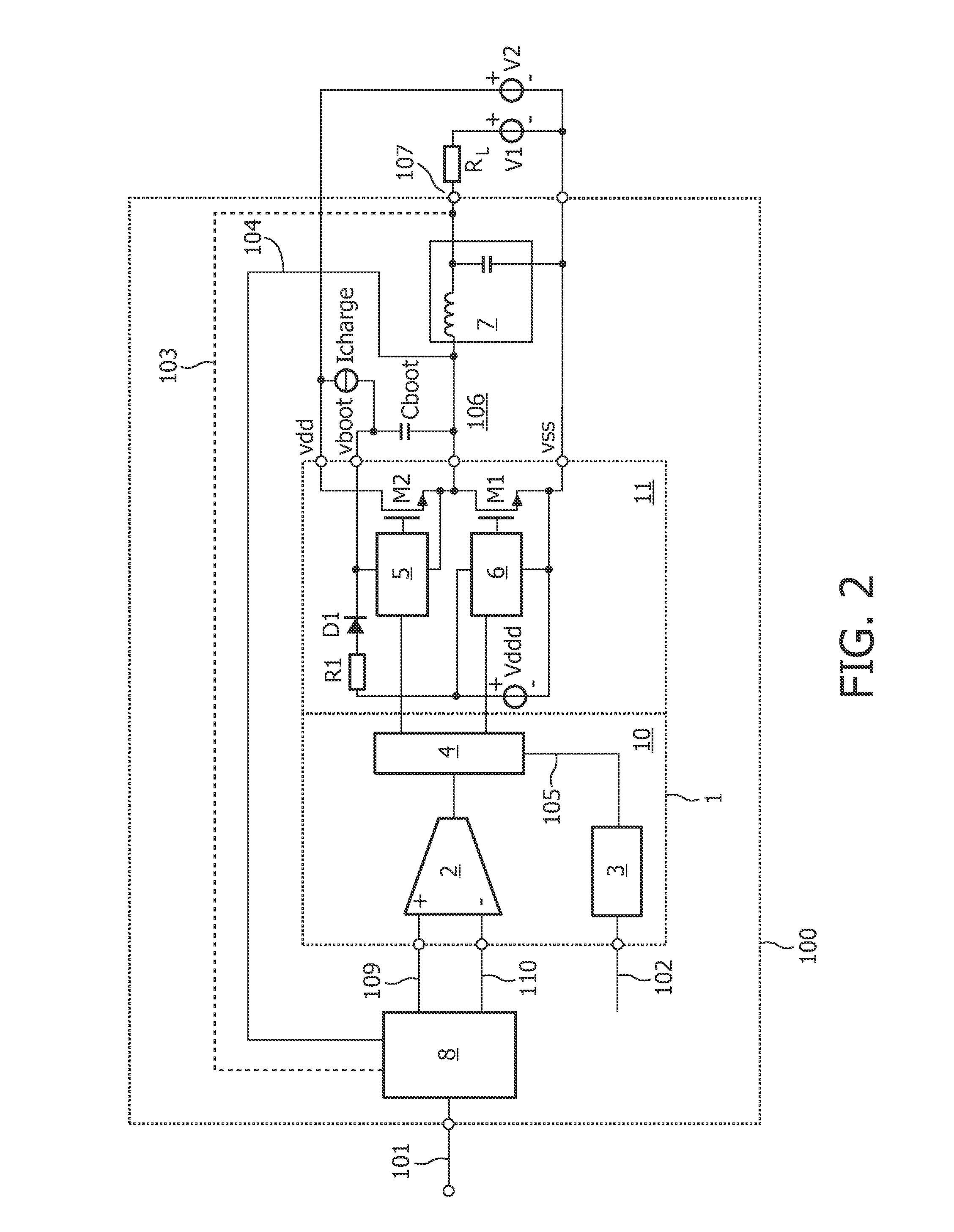
[0033]FIG. 2 shows a simplified schematic of the prior art that is substantially similar to FIG. 1. However, in order to overcome the hang up problem during a start-up of the self-oscillating class D system shown in FIG. 1, this conventional solution suggests to include an additional current source Icharge between the first end of the boot capacitor Cboot, i.e. vboot, and Vdd. According to this principle, the boot capacitor Cboot is precharged by the current source Icharge before the output power stage 11 is switched on. This principle is only applicable to supply voltages having the following relation:

V2>2×(Vtr+Vcs)

wherein Vtr is the minimum voltage for the charge guard protection across Cboot to release the high side driver (e.g. 9 V) and Vcs is the voltage drop across the current source Icharge (e.g. 1 V). Accordingly, only if V2 is greater than 20 V, the current source Icharge for charging the boot capacitor Cboot may be successfully applied. However, most of the applications re...


PUM


Abstract

The present invention relates to an electronic device that includes an integrated power comparator circuit (1) for a self-oscillating class D system (100). The integrated power comparator circuit (1) has a modulation stage (10), wherein the modulation stage (10) comprises a compensation circuit (40) for providing a compensation signal to the modulation stage, which is dimensioned for compensating a variation of a process parameter for smoothing initialization of the self-oscillating class D system (100).

Description

FIELD OF THE INVENTION[0001]The present invention relates to an electronic device for a self-oscillating class D system, more specifically to an electronic device for improved start up of a self-oscillating class D system.BACKGROUND OF THE INVENTION[0002]It is generally known in the art that class D amplifiers are useful for providing high output currents in order to drive loads as for example in audio applications. The class D systems convert audio signals into a sequence of high frequency pulses, wherein the output of a power output stage is a square wave with a duty cycle in accordance with an audio input signal. Some self-oscillating class D systems use pulse width modulators (PWM) in order to provide a sequence of pulses that varies in accordance with the audio signal's amplitude. The pulses switch the power output transistors at a specific frequency. Some self-oscillating class D systems use other kinds of modulation, such as density modulation or the like. The output of a cla...

Claims


Application Information

Patent Timeline
Patent Type & Authority Applications(United States)
IPC IPC(8): H03F3/217
CPCH03F1/26H03F1/304H03F3/217H03F3/2171H03F3/45085H03K7/08H03F2200/372H03F2200/375H03F2200/78H03F2203/45212H03F2203/45681H03F3/45596
Inventor BUITENDIJK, PIETER
Owner NXP BV
Why Eureka
Try Eureka