Circular waveguide antenna and circular waveguide array antenna

a technology of array antennas and waveguides, which is applied in the direction of waveguide horns, wing accessories, bathroom covers, etc., can solve the problems of inability to establish millimeter-wave communications, inability to machining the feeding portion and the radiating portion, and the shortage of frequency bands to be assigned to various communication devices, etc., to achieve the effect of improving radiation characteristics, reducing the cost of production, and improving the reflection loss characteristics of the antenna

Inactive Publication Date: 2010-09-16
OKI ELECTRIC IND CO LTD +1
View PDF2 Cites 34 Cited by
  • Summary
  • Abstract
  • Description
  • Claims
  • Application Information

AI Technical Summary

Benefits of technology

[0046]In the present invention, the circular waveguide is a conical horn with the diameter of the feeding side aperture at the feeding portion side being a, the diameter of the radiation aperture being d which is larger than the diameter of the feeding side aperture a, and the opening angle being 2α, When the wavelength of the central frequency of the

Problems solved by technology

In recent years, with the remarkable development of wireless communications technologies, there have been growing shortages of frequency bands to be assigned to various communication devices.
Without an antenna capable of transmitting and/or receiving millimeter-wave signals, millimeter-wave communications cannot be established.
The higher an employed frequency is—that is, the shorter a wavelength λ is—the smaller the diameter of a tube of the radiating portion is, and the more difficult is machining of the feeding portion and the radiating portion.
However, in the propagation mode TE11, an electric field distribution at the upper portion openings of the array elements is by no means an optimal electric field distribution.
Thus, there has been a problem in that it is not in any way possible to obtain optimal radiation characteristics.
Moreover, the conventional circular waveguide antenna illustrated in Non-patent Reference 1 has had a problem in that reflection loss characteris

Method used


Image

  • Circular waveguide antenna and circular waveguide array antenna
  • Circular waveguide antenna and circular waveguide array antenna
  • Circular waveguide antenna and circular waveguide array antenna

Examples


first embodiment

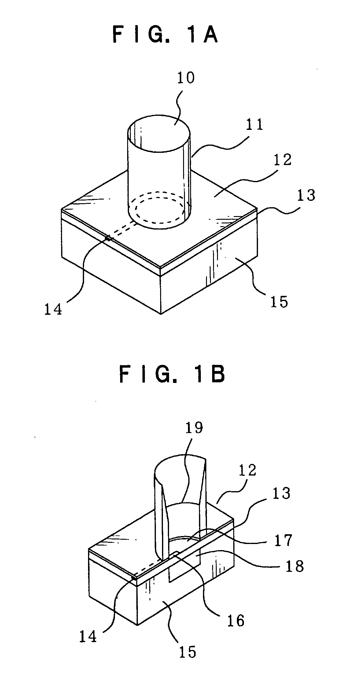
[0092]First, basic structure of a circular waveguide antenna relating to a first embodiment of the present invention will be described. A difference of circular waveguide antennas of the present invention from conventional circular waveguide antennas is the shape of an opening which radiates electromagnetic waves.

[0093]That is, while openings of conventional circular waveguide antennas are cut-off circular waveguides, an opening of a circular waveguide antenna of this invention is provided with a predetermined opening angle in accordance with an employed frequency, radiation gain is made as large as possible, and reflection losses at a feeding portion are minimized.

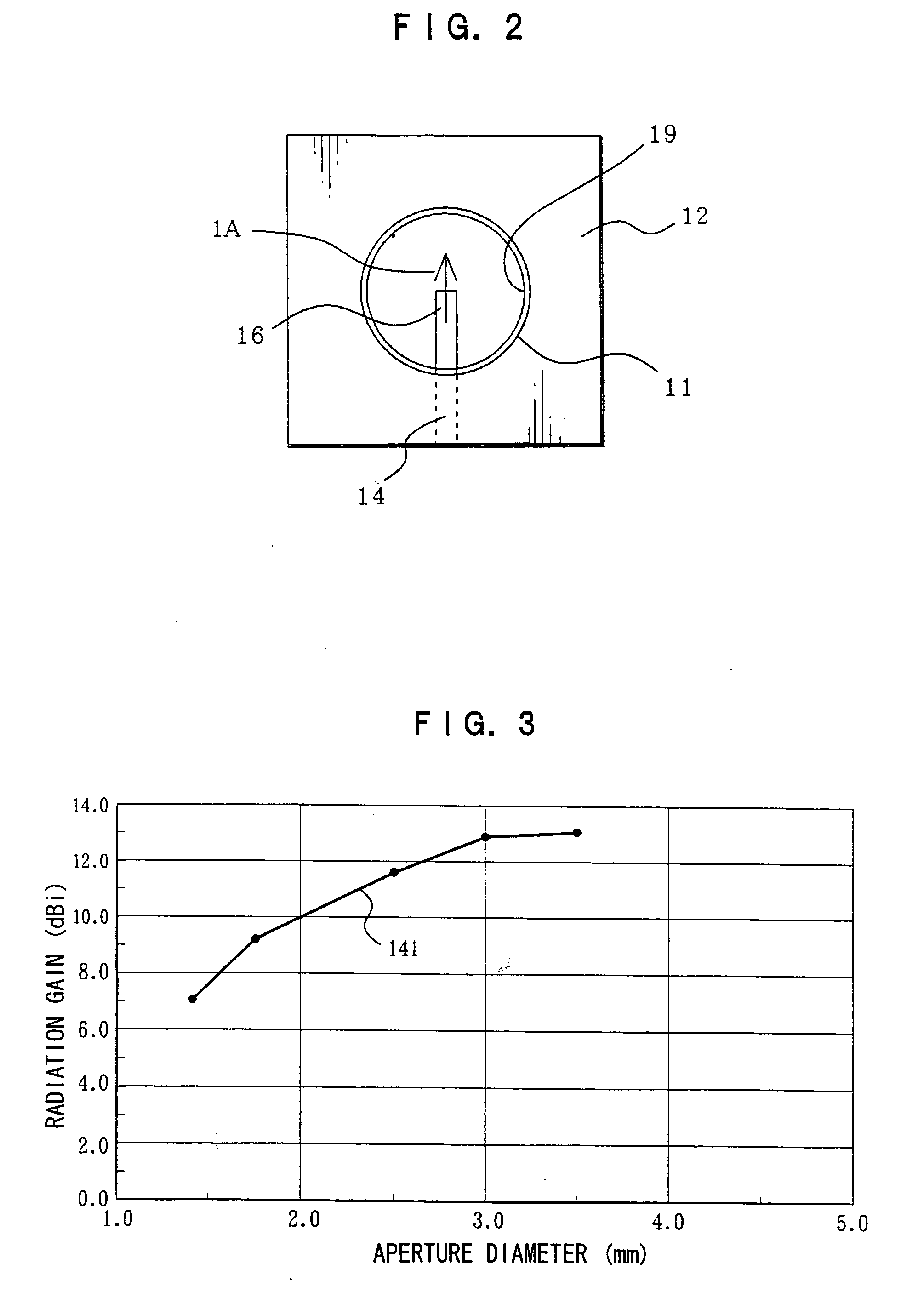
[0094]FIGS. 1A and 1B are structural views of a circular waveguide antenna which illustrates the first embodiment of the present invention. FIG. 1A is a perspective view of a horn-type circular waveguide antenna, and FIG. 1B is a side sectional view. FIG. 2 is a plan view of the circular waveguide antenna.

[0095]Structural...

second embodiment

[0138]In the first embodiment, feeding to the conical horn 11 is through the simple cut-off linear stripline distal end 16, and thus the circular waveguide antenna that is obtained is a circular waveguide antenna for linearly polarized waves.

[0139]However, when machining a cut-off stripline in a straight line for feeding, the circular waveguide antenna may be changed from a circular waveguide antenna for linearly polarized waves to a circular waveguide antenna for circularly polarized waves, and a circular waveguide antenna for circularly polarized waves can be obtained with hardly any deterioration in radiation gain, the reflection loss characteristic and the like. The present embodiment illustrates, of antennas for circularly polarized waves, a circular waveguide antenna for left-handed helically polarized waves.

[0140]FIG. 9 is a plan view showing structure of a circular waveguide antenna which illustrates the second embodiment of the present invention.

[0141]The structure is large...

third embodiment

[0154]Of circular waveguide antennas, a circular waveguide antenna for left-handed helically polarized light has been illustrated in the second embodiment, and the present embodiment relates to a circular waveguide antenna for right-handed helically polarized waves.

[0155]FIG. 10 is a plan view showing structure of a circular waveguide antenna which illustrates the third embodiment of the present invention. The present embodiment is very similar in structure to FIG. 9, which shows the second embodiment, and is a structure which adjusts phases of electric fields which are radiated from the propagation path distal ends such that the polarization of the radiated electromagnetic waves is rightward-twisting. Therefore, descriptions of structures will be omitted and only portions that are different will be described.

[0156]In FIG. 10, an aperture 90 of the circular waveguide antenna, which is viewed from directly above, is not a simple cylinder but actually has an opening angle. A stripline...


PUM


Abstract

A low-cost, compact circular waveguide array antenna which improves an antenna reflection loss characteristic and enables an improvement in radiation characteristics, particularly radiation gain. The circular waveguide array antenna includes feeding portions which feed electromagnetic waves to one ends of circular waveguides and radiation apertures which radiate the electromagnetic waves at the opposite ends. Each circular waveguide includes a conical horn, with a diameter of a feeding side aperture at the feeding portion end being a, a diameter of the radiation aperture being d, which is larger than the diameter a of the feeding side aperture, and an opening angle being 2α. If a wavelength of a central frequency of an employed frequency band is λ, then a value of α, which is half of the opening angle 2α, is set between 0.8×Arcsin(0.1349114/(d/λ)) and 1.2×Arcsin(0.1349114/(d/λ)).

Description

BACKGROUND OF THE INVENTION[0001]1. Field of the Invention[0002]The present invention relates to a circular waveguide antenna and a circular waveguide array antenna.[0003]2. Description of the Related Art[0004]Ordinarily, because reciprocal relationships are established at an antenna, transmission characteristics and reception characteristics are identical. Therefore, descriptions given hereafter are described for cases of transmission unless otherwise stated, and because cases of reception are the same, descriptions thereof will not be given.[0005]In recent years, with the remarkable development of wireless communications technologies, there have been growing shortages of frequency bands to be assigned to various communication devices. In order to compensate for this, technological developments which are necessary to transfer effective utilization of frequencies to higher ranges have become an urgent matter. For example, millimeter waves, which have conventionally been used virtual...

Claims


Application Information

Patent Timeline
IPC IPC(8): H01Q13/02H01Q13/00
CPCH01Q13/0258H01Q21/064H01Q21/0075A47K13/12A47K13/26E05Y2900/614
Inventor OU, HOK HUORNISHI, SEIJIOGAWA, HIROYOHAMAGUCHI, KIYOSHISHOJI, YOZO
Owner OKI ELECTRIC IND CO LTD
Why Eureka
Try Eureka