Display device

a display device and display technology, applied in the field of display devices, can solve the problems of duplicate components such as laser sources, inability to integrate into one piece, and restricted design and manufacturing of display devices, so as to improve efficiency and improve the application of display devices

Inactive Publication Date: 2010-09-16
ALVIS TECH
View PDF13 Cites 34 Cited by
  • Summary
  • Abstract
  • Description
  • Claims
  • Application Information

AI Technical Summary

Benefits of technology

[0005]Therefore it is a primary object of the present invention to provide a display device that includes a laser source, a pre-optics, a light scan member, and / or a post-optics. A switch-control beam splitter is disposed on the light path of the laser beam, after the light scan member. Thus after traveling through the beam splitter, the scanning light beam is divided into a reflected light beam and a transmitted light beam in two different light paths for different projection modes so as to generate virtual images and real images respectively. Thereby, users operate and switch the beam splitter to different mode so as to achieve both real image projection and virtual image projection. Therefore, the efficiency and applications of the display device are improved.

Problems solved by technology

However, the display devices of portables available now are only with a single display mode so that there are some problems raised in manufacturing or use.
The two post-optics 15, 35 used are also different from each other so that the design and manufacturing of the display devices are restricted and are unable to be integrated into one piece.
This also causes duplicate components such as laser sources 10 / 30, pre-optics 12 / 32, optical scanners 13 / 33 and waste of resources.
Furthermore, when users operate the portables, they may have various requirements at different time and space.
However, the display devices on portables available now only have a single mode and users have no more choices.
This leads to trouble and inconvenience in use.

Method used


Image

  • Display device
  • Display device
  • Display device

Examples


Embodiment Construction

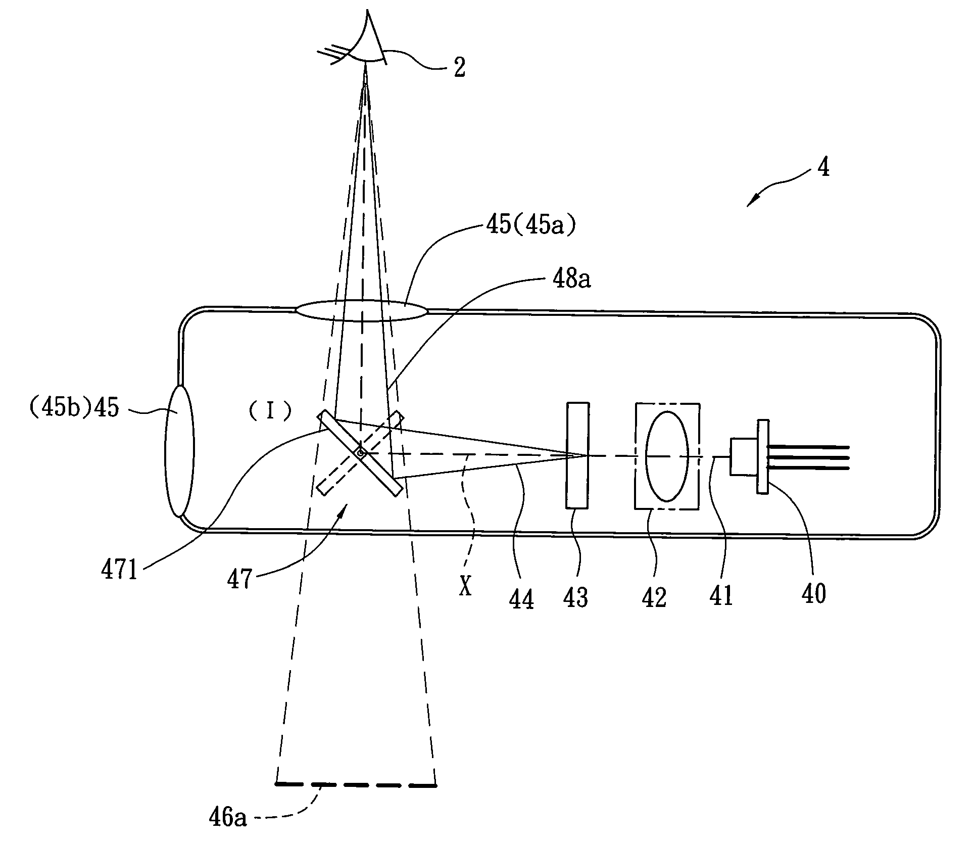
[0013]Refer to FIG. 3, FIG. 4&FIG. 5, a display device that switches between a real projection mode and a virtual projection mode can be applied to various portable electronics such as cell phones, personal digital assistants (PDA), handheld game consoles and notebooks. Similar to those of general display devices, the display device 4 includes basic components from a light source end to a projection end sequentially: a laser source 40 such as a red-green-blue laser source for emitting a laser beam 41, a pre-optics 42 formed by collimators, cylindrical mirrors, reflectors, zoom lens sets, or their combinations so as to form a parallel laser beam, arrange light paths of the laser beam or adjust laser beam focus, a light scan member 43 such as a MEMS mirror for converting the laser beam 41 into a scanning light beam 44, and / or a corresponding post-optics 45 (45a / 45b) formed by line scan lenses, enlarging lens set or their combinations. Yet in other embodiments of the present invention,...


PUM


Abstract

A display device is revealed. The display device includes a laser source for emitting a laser beam, a pre-optics for processing the laser beam, a light scan member such as a MEMS mirror for converting the processed laser beam into a scanning light beam, and / or a corresponding post-optics. A switch-control beam splitter is disposed on the light path of the laser beam, after the light scan member so as to divide the scanning light beam into a reflected light beam and a transmitted light beam. They are two different light paths and generate a virtual image as well as a real image respectively.

Description

BACKGROUND OF THE INVENTION[0001]The present invention relates to a display device, especially to a display device with a beam splitter that users can choose a real image projection mode or a virtual image projection mode.[0002]The portable devices available now such as cell phones, personal digital assistants (PDA), handheld game consoles and notebooks are all disposed with display devices. Generally, the display devices show either real images or virtual images. Refer to FIG. 1, a virtual image display device1 shows images in a virtual projection mode. The virtual image display device 1 includes a laser source 10 such as a red-green-blue (R, G, B) laser source for emitting tricolor laser beam 11. The laser beam 11 firstly passes a pre-optics 12 formed by collimators, cylindrical mirrors, reflectors, zoom lens sets, or their combinations for forming parallel laser beam, light path arrangement, or laser beam focus adjustment. Then by a light scanner 13 such as MEMS mirrors (micro el...

Claims


Application Information

Patent Timeline
Patent Type & Authority Applications(United States)
IPC IPC(8): G03B21/28
CPCH04N9/3129G03B21/28
Inventor CHEN, GUO-ZENWEN, MING-HUACHEN, CHIH-HSIAO
Owner ALVIS TECH
Why Eureka
Try Eureka