Quantitative phase-imaging systems

Inactive Publication Date: 2010-09-16
UT BATTELLE LLC
View PDF16 Cites 14 Cited by
  • Summary
  • Abstract
  • Description
  • Claims
  • Application Information

AI Technical Summary

Problems solved by technology

Unfortunately, the length, width, and depth of an object are measured by some systems through the physical rotation of the object.
The system may require complex

Method used


Image

  • Quantitative phase-imaging systems
  • Quantitative phase-imaging systems
  • Quantitative phase-imaging systems

Examples


Embodiment Construction

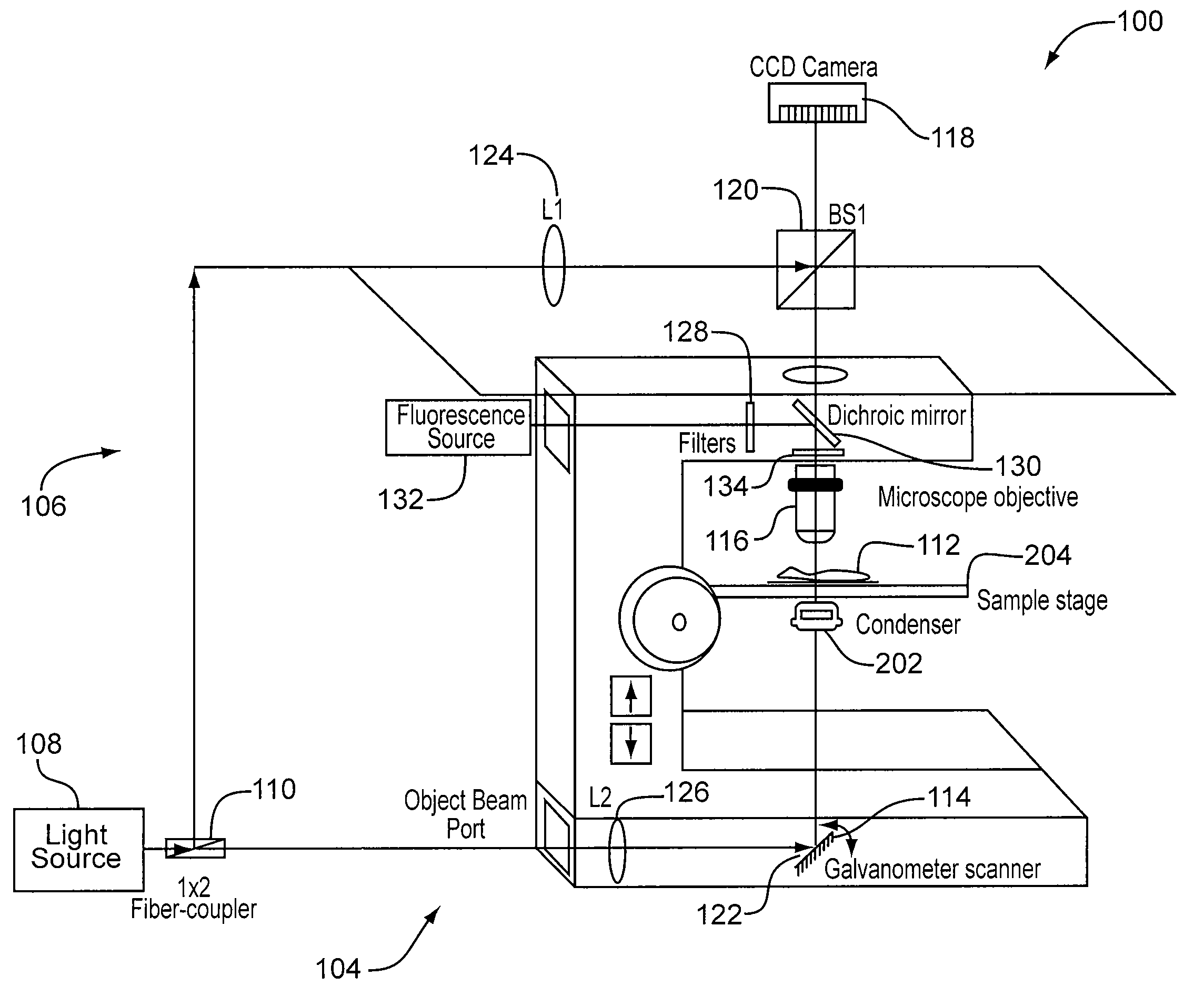
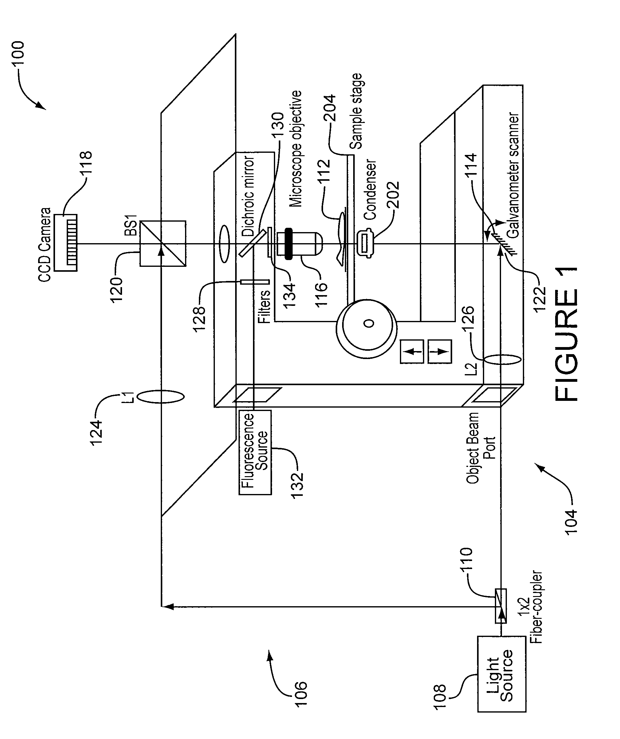
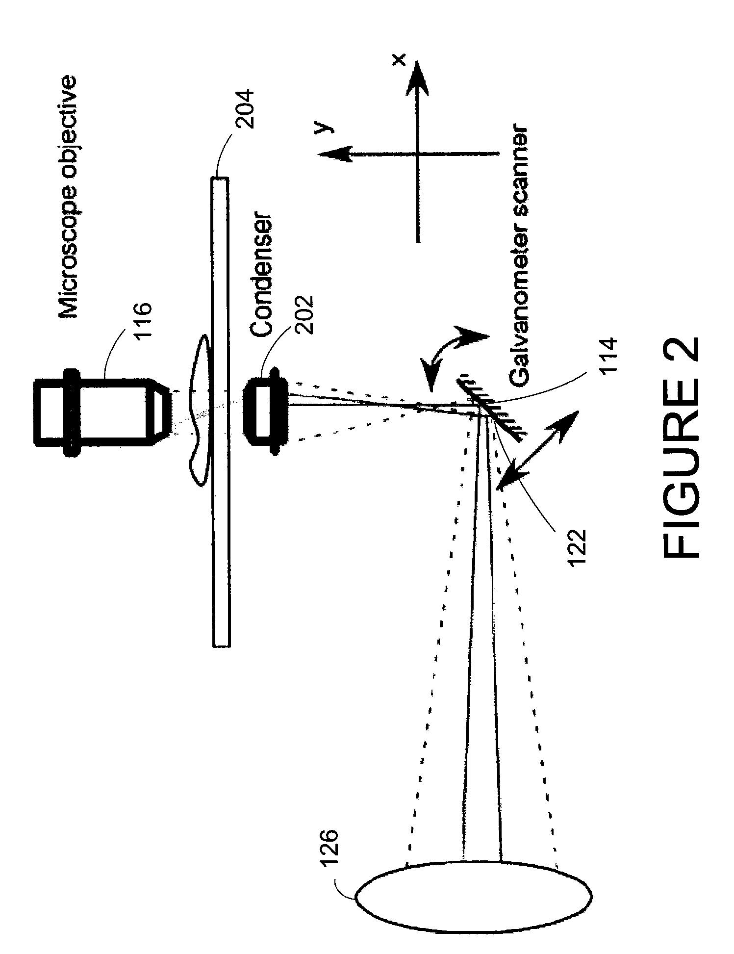
[0015]Quantifying optical path length changes may detect refractive indexes or optical thickness variations with a vertical and horizontal resolution of a few nanometers. The quantification may be used to investigate morphological variations associated with dynamic anthropologic processes, ecologic processes, and biological processes including drug delivery, disease progression, and / or other pathological or scientific occurrences.

[0016]An optical system may include one or more digital optical interferometers that may not require multiple image acquisitions through a sequence of illuminating projections. When reconstructed, the images may provide high resolution data that may establish length, width, and / or depth information. The phase information may establish a refractive index and / or optical thickness of an object or sample. The data captured may be retained within a local or a remote memory or database that facilitates real-time imaging and viewing (e.g., through a display) local...


PUM


Abstract

An optical system performs imaging in a transmissive and reflective mode. The system includes an optical interferometer that generates interference phenomena between optical waves to measure multiple distances, thicknesses, and indices of refraction of a sample. Measurements are made through a galvanometer that scans a pre-programmed angular arc. An excitation-emission device allows an electromagnetic excitation and emission to pass through an objective in optical communication with the sample. An electromagnetic detector receives the output of the optical interferometer and the excitation-emission device to render a magnified three dimensional image of the sample.

Description

RELATED APPLICATION [0001]This application is related to U.S. application Ser. No. ______ (Attorney Docket No. 13489 / 79 (ID 2153)) filed on Mar. 16, 2009, entitled “Quantitative Phase-Contrast and Excitation-Emission Systems” and U.S. application Ser. No. ______ (Attorney Docket No. 13489 / 95 (ID 2150.0)) filed on Mar. 16, 2009, entitled “Three Wavelength Quantitative Imaging Systems,” which are incorporated by reference.BACKGROUND OF THE INVENTION[0002]1. Technical Field[0003]This disclosure relates to optical systems and particularly to systems that generate three-dimensional visual images.[0004]2. Related Art[0005]The need for accurate and full-field measurements of objects in life sciences is increasing. Magnified views of living organisms may promote diagnostics, treatment, and prevention of disease of the body and mind. Full-field views promote many branches of science including anthropology and ecology that study the organisms' life processes, relationships, and environment.[0...

Claims


Application Information

Patent Timeline
IPC IPC(8): G01N21/00
CPCG01B9/021G01B11/0675G01N21/45G01N21/453G01N21/6458G01B9/02069G01B9/02012G01B9/02007G01B9/02027G01B9/02024G01N2021/1787
Inventor MANN, CHRISTOPHER J.BINGHAM, PHILIP R.GLEASON, SHAUN S.
Owner UT BATTELLE LLC
Why Eureka
Try Eureka