Method and Apparatus for Over-voltage Protection With Breakdown-Voltage Tracking Sense Element

a technology of breakdown voltage and sense element, applied in the direction of emergency protective arrangements for limiting excess voltage/current, arrangements responsive to excess voltage, pulse techniques, etc., can solve the problem of increasing the breakdown voltage margin when designing the power device, adding size and cost, etc. problem, to achieve the effect of higher breakdown voltag

Inactive Publication Date: 2010-09-16
ADVANCED ANALOGIC TECHNOLOGIES INCORPORATED
View PDF4 Cites 27 Cited by
  • Summary
  • Abstract
  • Description
  • Claims
  • Application Information

AI Technical Summary

Benefits of technology

[0007]In a preferred embodiment, the sense element may also serve as the clamp device that protects power transistor from damage during EOS and ESD events. In another embodiment, a clamp element is included in parallel with the power transistor and sense element. The clamp element preferably has a construction similar to the sense element, and may have an identical drift region length (providing very similar breakdown voltage) or a slightly longer drift region length (to provide a slightly higher breakdown voltage) compared to the sense element. The clamp element is preferably much larger than the sense element so that it can withstand high currents without failure. For this embodiment, the clamp element absorbs additional energy reducing the breakdown voltage current in the sense element and protecting the circuitry of the control circuit

Problems solved by technology

One shortcoming of this approach is the addition of the external resistors, which adds size and cost to the solution.
Another problem is the inability to trim out the variation in the resistor values, which necessitates the use of expensive, high-precision resistors and / or increased tolerances on the OVP specification.
The clamping function in PICs is typically accomplished by a diode structure that has a different construction than that of the power device it is protecting, which has the disadvantage of exhibiting process variation that is not aligned with the process variation of the power device, such that increased breakdown voltage (BV) margin is required when designing the power device.

Method used


Image

  • Method and Apparatus for Over-voltage Protection With Breakdown-Voltage Tracking Sense Element
  • Method and Apparatus for Over-voltage Protection With Breakdown-Voltage Tracking Sense Element
  • Method and Apparatus for Over-voltage Protection With Breakdown-Voltage Tracking Sense Element

Examples


Embodiment Construction

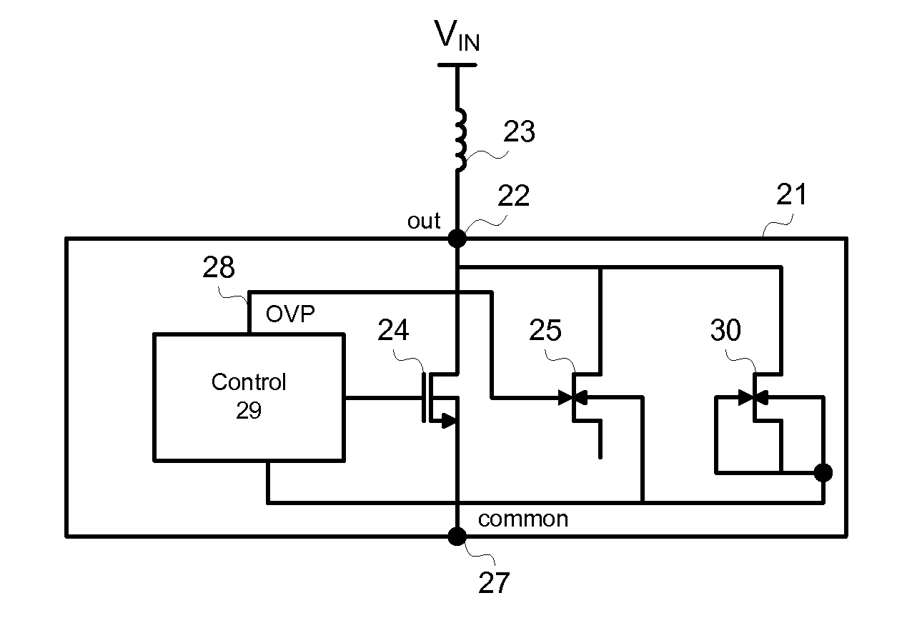
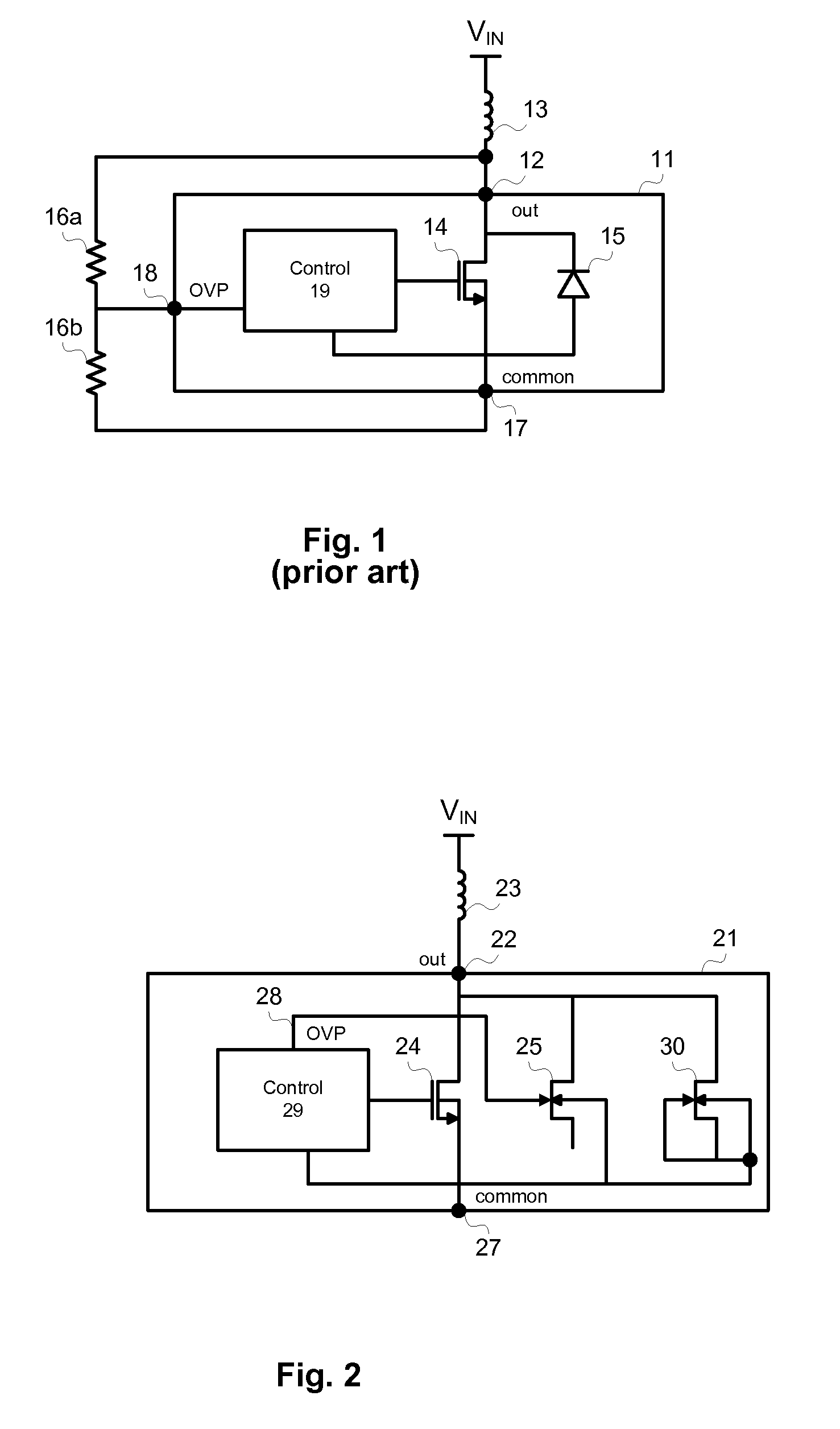
[0013]FIG. 2 shows one embodiment of the present invention. PIC 21 has a main output terminal 22 through which an external load 23 is controlled by a power transistor 24, which is protected by a parallel OVP sense element 25. Sense element 25 has a construction that is similar to that of power transistor 24, except that sense element 25 is tailored to have a lower BV than that of power transistor 24. In a preferred embodiment, power transistor 24 comprises a drift region that primarily determines the BV of this transistor, and sense element 25 has a similar drift region but with a shorter drift region length and / or changes in field plating that provide a lower BV. The advantage of this construction is that the BVs of power transistor 24 and sense element 25 will track each other with process variation and temperature. This greatly reduces the required voltage stack-up that must account for differences in these BVs over the full range of process variation and operating temperatures. ...


PUM


Abstract

A power integrated circuit with internal over-voltage protection includes a power transistor monolithically integrated with a sense element and a control circuit. The power transistor is connected to an output terminal that is connected (or is connectable) to an external load. The sense element is connected to the output terminal in parallel with the power transistor. The sense element is constructed to be similar to the power transistor except that the sense element has a lower breakdown voltage. When the voltage of the output terminal exceeds the breakdown voltage of the sense element a breakdown current flows from the gate of the sense element to the control circuit. Inside the control circuit, a comparator or other over-voltage protection circuit monitors this feedback and controls the power transistor accordingly to protect the power integrated circuit from damage.

Description

BACKGROUND OF THE INVENTION[0001]Power integrated circuits (PICs) are used in many applications. PICs typically combine control circuitry with one or more monolithically-integrated power transistors. Power transistors are capable of handling voltages and / or currents that are significantly higher than standard analog or digital integrated circuit devices. A common requirement in the design of PICs is to monitor the voltage on one or more output terminals and provide protection for the PIC if this voltage exceeds a safe level. It is important to implement this over-voltage protection (OVP) function in a low-cost, compact manner and to minimize tolerances in order to minimize the design margin required for the power transistors. The power transistors in PICs typically have a clamp structure placed in parallel with each power transistor. The clamp is designed to have a lower breakdown voltage than that of the power transistor, so that the clamp, rather than the power device, takes the e...

Claims


Application Information

Patent Timeline
Patent Type & Authority Applications(United States)
IPC IPC(8): H02H3/20
CPCH01L21/823418H01L27/0266H01L29/402H03K2217/0072H01L29/808H03K17/08142H03K17/0822H01L29/7825
Inventor DISNEY, DONALD
Owner ADVANCED ANALOGIC TECHNOLOGIES INCORPORATED
Why Eureka
Try Eureka