Failure recovery method, computer system, and storage medium recorded failure recovery program for a stream data processing system

a data processing system and failure recovery technology, applied in data switching networks, frequency-division multiplexes, instruments, etc., can solve the problems of large overhead, large network load, and large overhead of standby systems, and achieve the effect of quick recovery of computer systems

Inactive Publication Date: 2010-09-16
HITACHI LTD
View PDF3 Cites 17 Cited by
  • Summary
  • Abstract
  • Description
  • Claims
  • Application Information

AI Technical Summary

Benefits of technology

[0019]It is an object of this invention to provide a technology for quickly recovering a stream data processing system without increasing load on a standby system and a network if a failure occurs in an active system.
[0021]According to the representative embodiment of this invention, it is possible to quickly recover the computer system from the failure while suppressing the load on the network and resource consumption on the standby system (second computer).

Problems solved by technology

However, according to the technology disclosed in above-described “High-Availability Algorithms for Distributed Stream Processing”, in the ActiveStandby scheme, the standby system is operating in the same manner as the active system even in the normal mode in which the active system is operating normally, which leads to a problem that many resources may be consumed.
Further, in the PassiveStandby scheme, all of contents of the memory within the stream data processing system need to be copied to the standby system constantly, and hence huge load may be imposed on a network by transferring an enormous memory amount therethrough.
In addition, the standby system may produce huge overhead by receiving an enormous amount of information.

Method used


Image

  • Failure recovery method, computer system, and storage medium recorded failure recovery program for a stream data processing system
  • Failure recovery method, computer system, and storage medium recorded failure recovery program for a stream data processing system
  • Failure recovery method, computer system, and storage medium recorded failure recovery program for a stream data processing system

Examples


Embodiment Construction

[0045]Hereinafter, detailed description is made of an embodiment for carrying out this invention by referring to the accompanying drawings.

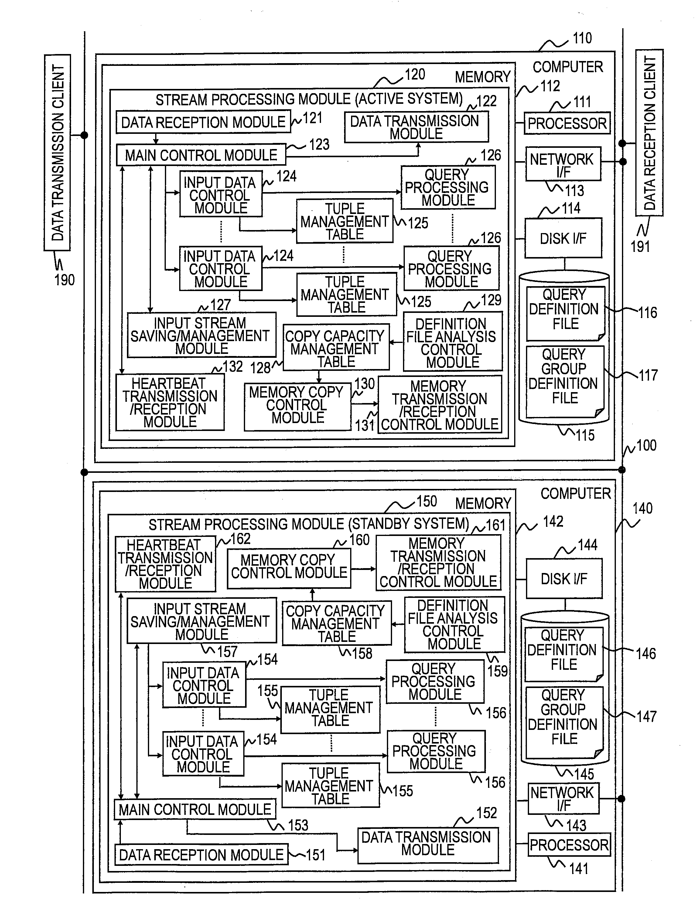
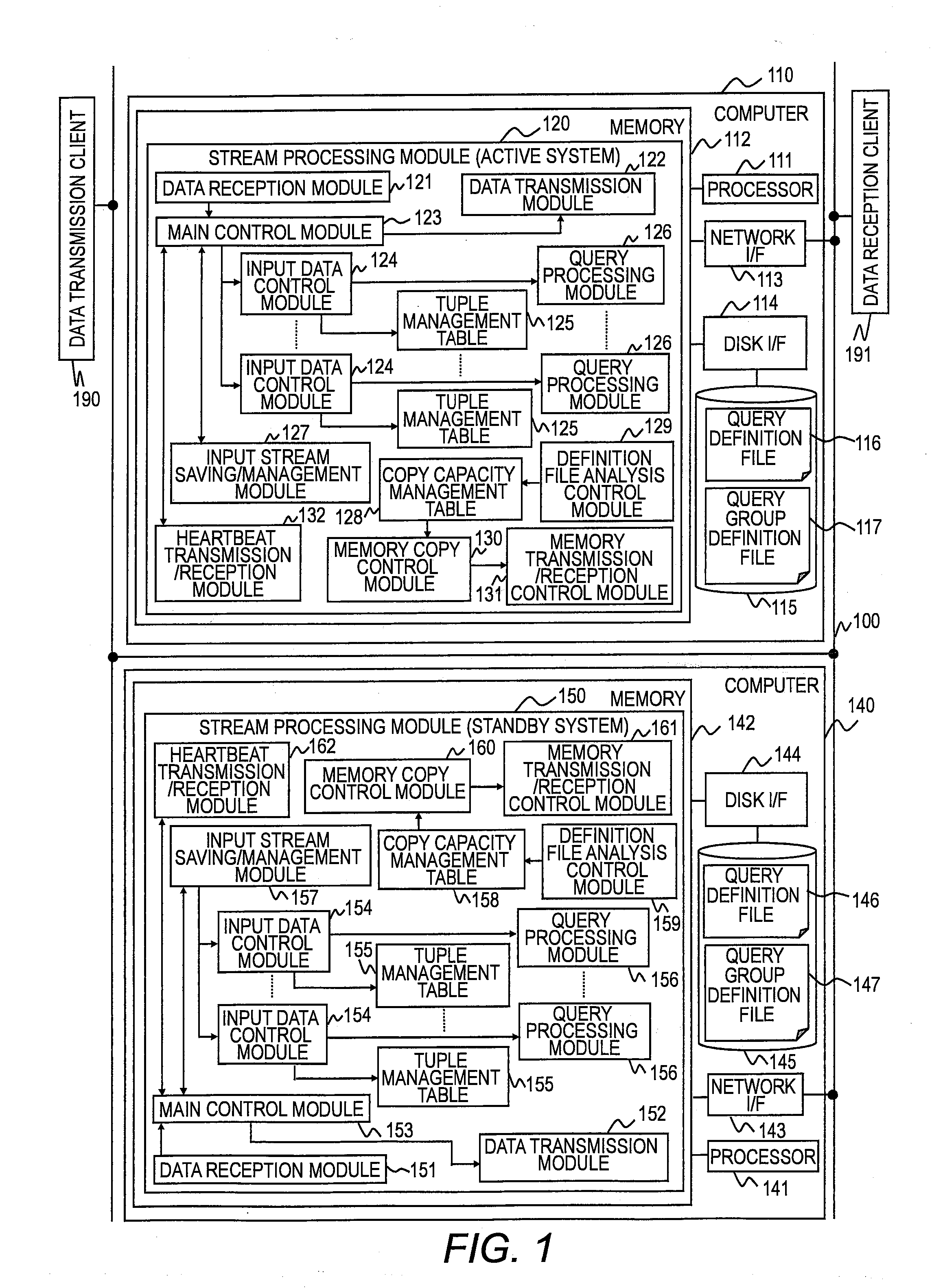
[0046]FIG. 1 is a diagram illustrating a configuration of a computer system and relationships between respective components thereof according to the embodiment of this invention.

[0047]The computer system according to the embodiment of this invention includes a computer 110 of an active system and a computer 140 of a standby system. The computer 110 of the active system and the computer 140 of the standby system are connected to each other via a network 100. The computer 140 of the standby system processes stream data in place of the computer 110 of the active system in a case where a failure has occurred on the computer 110 of the active system or other such case.

[0048]Further connected to the computer 110 of the active system and the computer 140 of the standby system are a data transmission client 190 and a data reception client 191. The data t...


PUM


Abstract

Provided is a failure recovery method for switching to a standby system if a failure occurs in an active system, which allows reduction of loads on the standby system and a network. A computer system, which receives data to which timestamp information is appended in a chronological order and processes the received data by registered queries, includes the active system for processing the received data and the standby system for processing the received data instead of the active system upon occurrence of a failure. The active system processes the received data by the respective queries according to a predefined sequence, and transmits results obtained from the received data by the respective queries to the standby system as intermediate data on a query basis at a predetermined timing. The standby system restores the data by processing the received data and the intermediate data if a failure occurs in the active system.

Description

CLAIM OF PRIORITY[0001]The present application claims priority from Japanese patent application JP 2009-060783 filed on Mar. 13, 2009, the content of which is hereby incorporated by reference into this application.BACKGROUND OF THE INVENTION[0002]This invention relates to a technology for recovering a failure in a stream data processing system.[0003]Up to now, a database management system (hereinafter, referred to as “DBMS”) plays a dominant role in data management for a corporate information system. In the DBMS, data to be processed is stored in a storage system, and a highly-reliable processing typified by a transaction processing is realized for the stored data.[0004]In contrast, in recent years, there is an increasing demand for a data processing system which performs a real-time processing on a large amount of data arriving from moment to moment. For example, in a case of a financial application for assisting stock trading, it is one of the most important challenges for the sys...

Claims


Application Information

Patent Timeline
Patent Type & Authority Applications(United States)
IPC IPC(8): H04L12/26
CPCG06F11/2038G06F2201/835G06F11/2097G06F11/2048
Inventor TAKAHASHI, NORIAKIWATANABE, SATORUHANAI, TOMOHIRO
Owner HITACHI LTD
Why Eureka
Try Eureka