
Electrical contact for occlusive device delivery system

a technology of electric contact and occlusive device, applied in the field of system and delivery device, can solve the problems of less than optimal conductivity, conductive instability at the junction between the electrical contact, and electrically severable junctions are susceptible to electrolysis and disintegration, so as to improve mechanical stability and reduce variability in detachment times

Inactive Publication Date: 2010-09-16
STRYKER CORP +1
View PDF52 Cites 38 Cited by
  • Summary
  • Abstract
  • Description
  • Claims
  • Application Information

AI Technical Summary

Benefits of technology

[0008]Embodiments of the present invention provide improved mechanical stability at the junction between the electrical contact and the delivery wire, while still providing for consistent detachment of embolic elements in the desired location. Embodiments of the present invention also reduce variability in detachment times for occlusive devices, providing conductive stability and alternative return and / or ground electrode configurations that do not utilize a separate, external return electrode, such as a patch or grounding needle.

Problems solved by technology

An electrolytically severable junction is susceptible to electrolysis and disintegrates when the pusher wire is electrically charged in the presence of an ionic solution, such as blood or other bodily fluids.
Perceived problems with current embolic detachment schemes include mechanical weakness at the junction between the electrical contact and the delivery wire.
Another perceived problem is conductive instability at the junction between the electrical contact and the delivery wire.
For example, the relatively small amount of contact between the electrical contact and the delivery wire can result in less than optimal conductivity and variability in conductivity, which can lead to variability in detachment times.
Another perceived problem with some current embolic detachment devices is that a separate return or ground electrode is used to complete the electrical circuit between the external power supply and the electrolytically detachable coil.
The use of a separate, return or ground electrode does, however, introduce variability into the detachment time(s) of the occlusive coils.
Also, for grounding needles that are placed in the groin area of the patient, some patients experience discomfort or pain.

Method used


Image

  • Electrical contact for occlusive device delivery system
  • Electrical contact for occlusive device delivery system
  • Electrical contact for occlusive device delivery system

Examples


Embodiment Construction

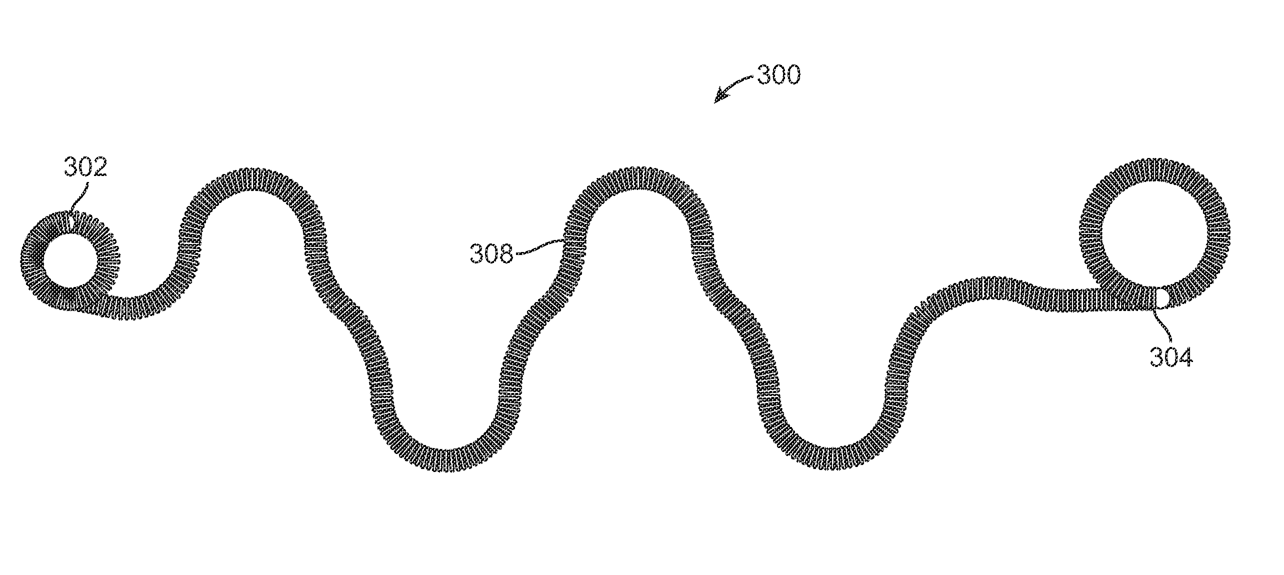
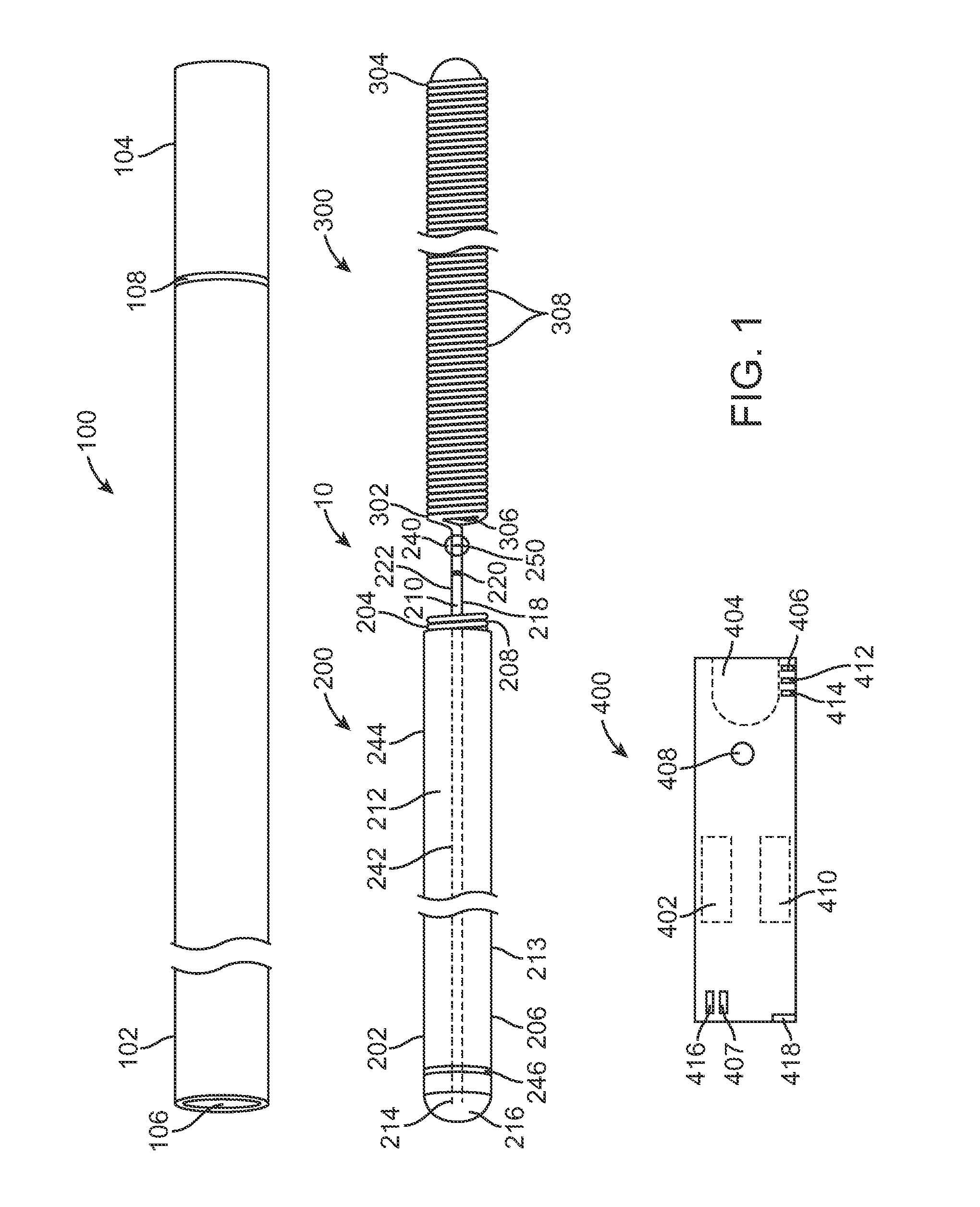
[0017]FIG. 1 illustrates an occlusive coil delivery system 10 according to one embodiment. The system 10 includes a number of subcomponents or sub-systems. These include a delivery catheter 100, a delivery wire assembly 200, an occlusive coil 300, and a power supply 400. The delivery catheter 100 includes a proximal end 102, a distal end 104, and a lumen 106 extending between the proximal and distal ends 102, 104. The lumen 106 of the delivery catheter 100 is sized to accommodate axial movement of the delivery wire assembly 200. Further, the lumen 106 is sized for the passage of a guidewire (not shown) which may optionally be used to properly guide the delivery catheter 100 to the appropriate delivery site.

[0018]The delivery catheter 100 may include a braided-shaft construction of stainless steel flat wire that is encapsulated or surrounded by a polymer coating. For example, HYDROLENE® is one exemplary polymer coating that may be used to cover the exterior portion of the delivery ca...


PUM


Abstract

An occlusive coil delivery system includes a delivery wire having a distal end coupled to an occlusive device via an electrolytically severable junction, and an electrical contact secured to a proximal end of the delivery wire, which has a non-linear configuration so as to strengthen a mechanical connection with the electrical contact and / or increase electrical conductivity with the electrical contact over a linear configuration. The configuration may be, by way of non-limiting examples, a “U” shape, a spiral, a knot, or a twisted wire. The electrical contact is a conductive material that substantially envelopes the proximal end configuration of the delivery wire.

Description

RELATED APPLICATION DATA[0001]The present application claims the benefit under 35 U.S.C. §119 to U.S. Provisional application Ser. No. 61 / 160,166 filed Mar. 13, 2009. The foregoing application is hereby incorporated by reference into the present application in its entirety.FIELD OF THE INVENTION[0002]The field of the invention generally relates to systems and delivery devices for implanting vaso-occlusive devices for establishing an embolus or vascular occlusion in a vessel of a human or veterinary patient.BACKGROUND OF THE INVENTION[0003]Vaso-occlusive devices or implants are used for a wide variety of reasons, including treatment of intra-vascular aneurysms. Commonly used vaso-occlusive devices include soft, helically wound coils formed by winding a platinum (or platinum alloy) wire strand about a “primary” mandrel. The relative stiffness of the coil will depend, among other things, on its composition, the diameter of the wire strand, the diameter of the primary mandrel, and the p...

Claims


Application Information

Patent Timeline
Patent Type & Authority Applications(United States)
IPC IPC(8): A61M29/00
CPCA61B17/12022A61B17/12109A61B2017/12068A61B2017/00477A61B2017/12063A61B17/12145
Inventor GUO, LANTAONGO, TRADAO, JIMMY
Owner STRYKER CORP
Features
  • Generate Ideas
  • Intellectual Property
  • Life Sciences
  • Materials
  • Tech Scout
  • Unparalleled Data Quality
  • Higher Quality Content
  • 60% Fewer Hallucinations
Learn More