
Method of manufacturing a package, and package, electronic device, piezoelectric vibrator, oscillator, electronic apparatus, and radio clock

a manufacturing method and technology of piezoelectric vibrators, applied in the direction of generators/motors, piezoelectric/electrostrictive transducers, transducer types, etc., can solve the problems of high cost, low manufacturing efficiency, and high cost of time and effort, so as to reduce cost, improve quality, and manufacture efficiently

Inactive Publication Date: 2010-09-23
SII CRYSTAL TECH
View PDF23 Cites 4 Cited by
  • Summary
  • Abstract
  • Description
  • Claims
  • Application Information

AI Technical Summary

Benefits of technology

[0007]In other words, in a case where the base substrate on the side where the piezoelectric vibrating strip is mounted is manufactured, for example, of glass for manufacturing the piezoelectric vibrator in the related art, a number of complicated steps such as a step of forming depressions for a cavity on the side opposing the lid portion by photolithography technique, a step of forming drawn electrodes, a step of forming mount pads for fixing the piezoelectric vibrating strips, and a step of forming a bonding film must be performed, and hence manufacturing efficiency is low at much expense in time and effort, and a cost increase is resulted.
[0035]Furthermore, according to the oscillator, the electronic apparatus, and the radio clock according to the present invention, since the piezoelectric vibrator described above is provided, increase in quality and reduction in cost can be achieved in the same manner.

Problems solved by technology

However, the piezoelectric vibrator in the related art as described above still has the following problem.
In other words, in a case where the base substrate on the side where the piezoelectric vibrating strip is mounted is manufactured, for example, of glass for manufacturing the piezoelectric vibrator in the related art, a number of complicated steps such as a step of forming depressions for a cavity on the side opposing the lid portion by photolithography technique, a step of forming drawn electrodes, a step of forming mount pads for fixing the piezoelectric vibrating strips, and a step of forming a bonding film must be performed, and hence manufacturing efficiency is low at much expense in time and effort, and a cost increase is resulted.
Also, since an isotropic etching method is employed when forming the depression for a cavity on the base substrate, corners are rounded and hence machined surfaces with sharp edges can hardly be achieved.
Therefore, it may affect adversely to hermeticity in the interior of the cavity.

Method used


Image

  • Method of manufacturing a package, and package, electronic device, piezoelectric vibrator, oscillator, electronic apparatus, and radio clock
  • Method of manufacturing a package, and package, electronic device, piezoelectric vibrator, oscillator, electronic apparatus, and radio clock
  • Method of manufacturing a package, and package, electronic device, piezoelectric vibrator, oscillator, electronic apparatus, and radio clock

Examples


Embodiment Construction

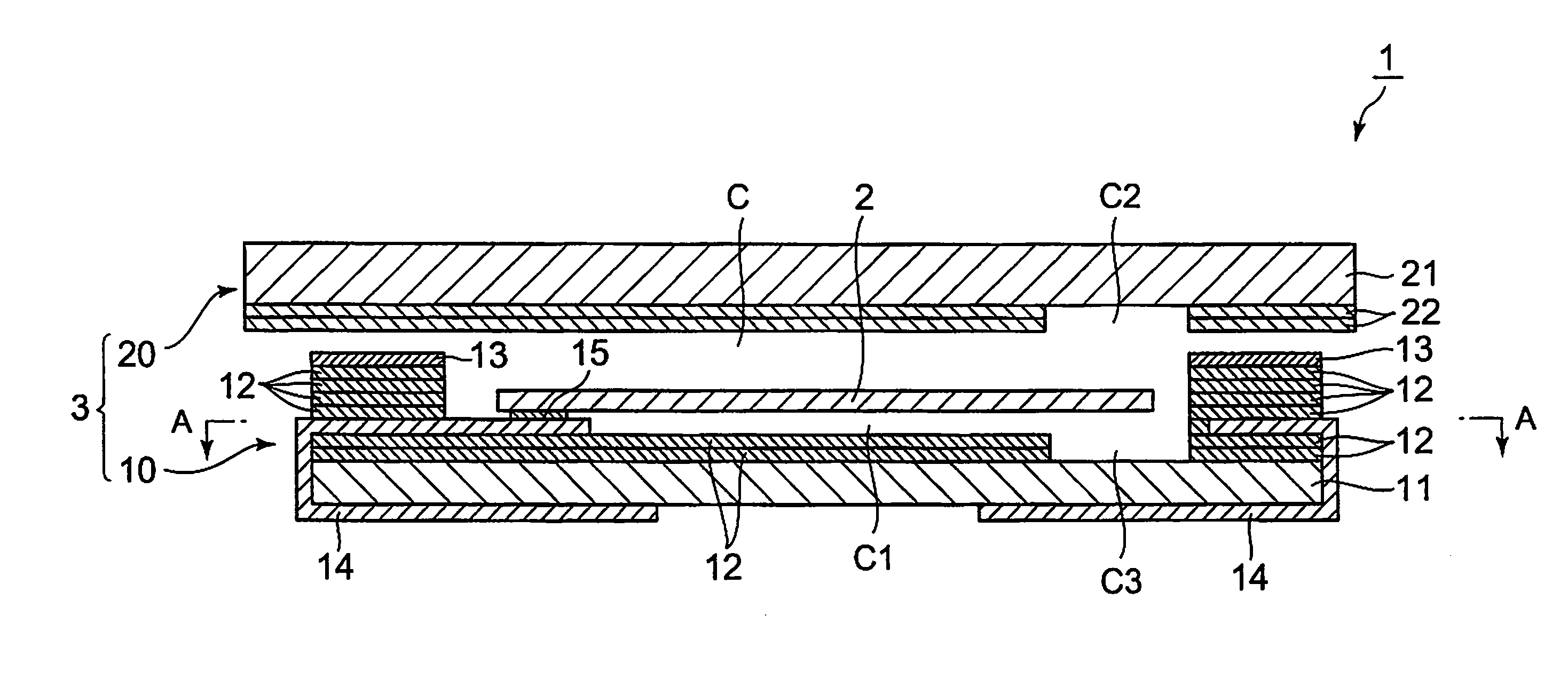
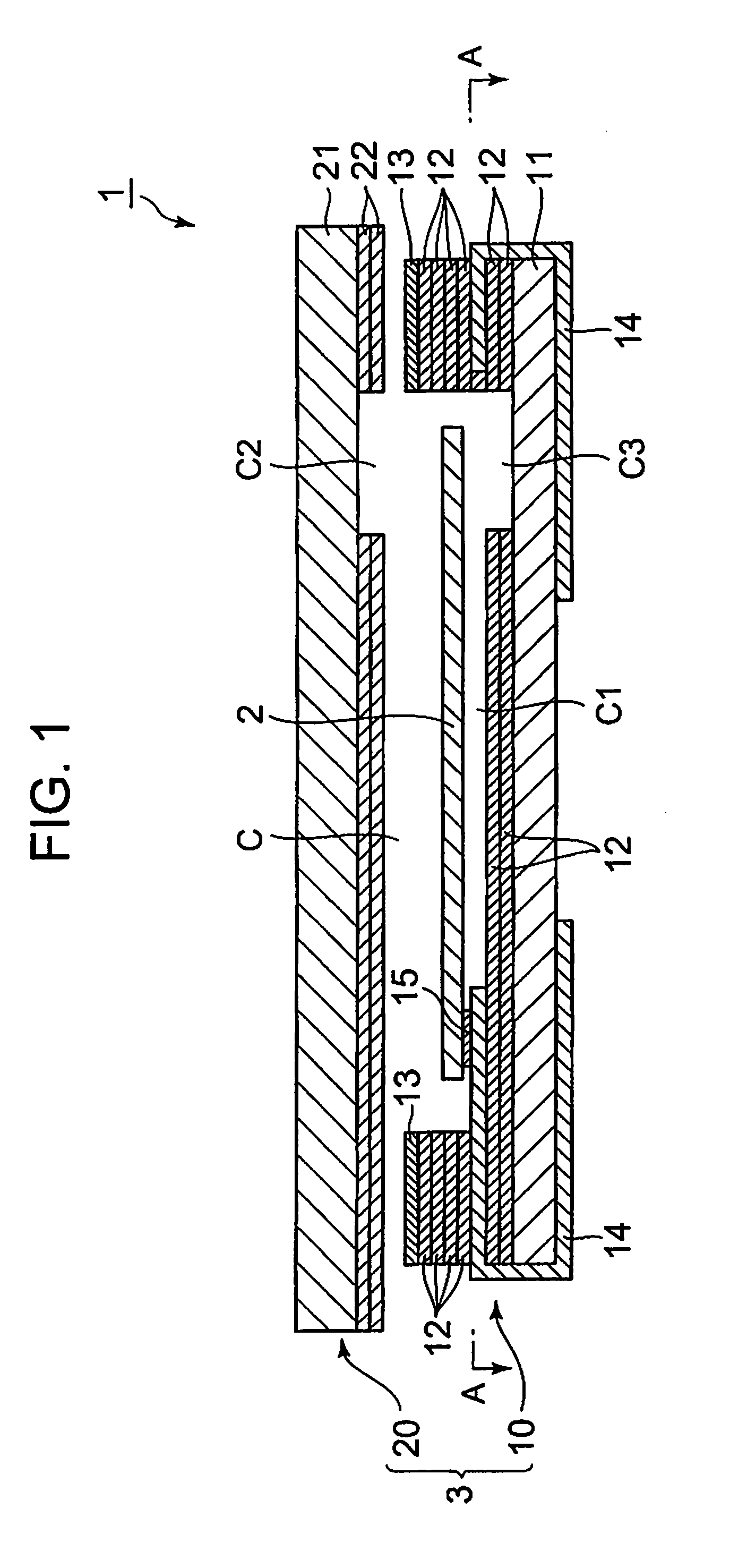
[0050]Referring now to FIG. 1 to FIG. 11, an embodiment of the present invention will be described. In this embodiment, a case where a package is applied to a piezoelectric vibrator will be described as an example.

[0051]A piezoelectric vibrator 1 according to this embodiment is a piezoelectric vibrator of a surface-mounted type (two-layer structure type), and includes a piezoelectric vibrating strip 2 and a package 3 having the piezoelectric vibrating strip 2 stored in a cavity C formed in the interior thereof as shown in FIG. 1. In FIG. 1, a state in which a base substrate 10 and a lid substrate 20, described later, are slightly apart from each other is shown for the sake of easy understanding of the drawing.

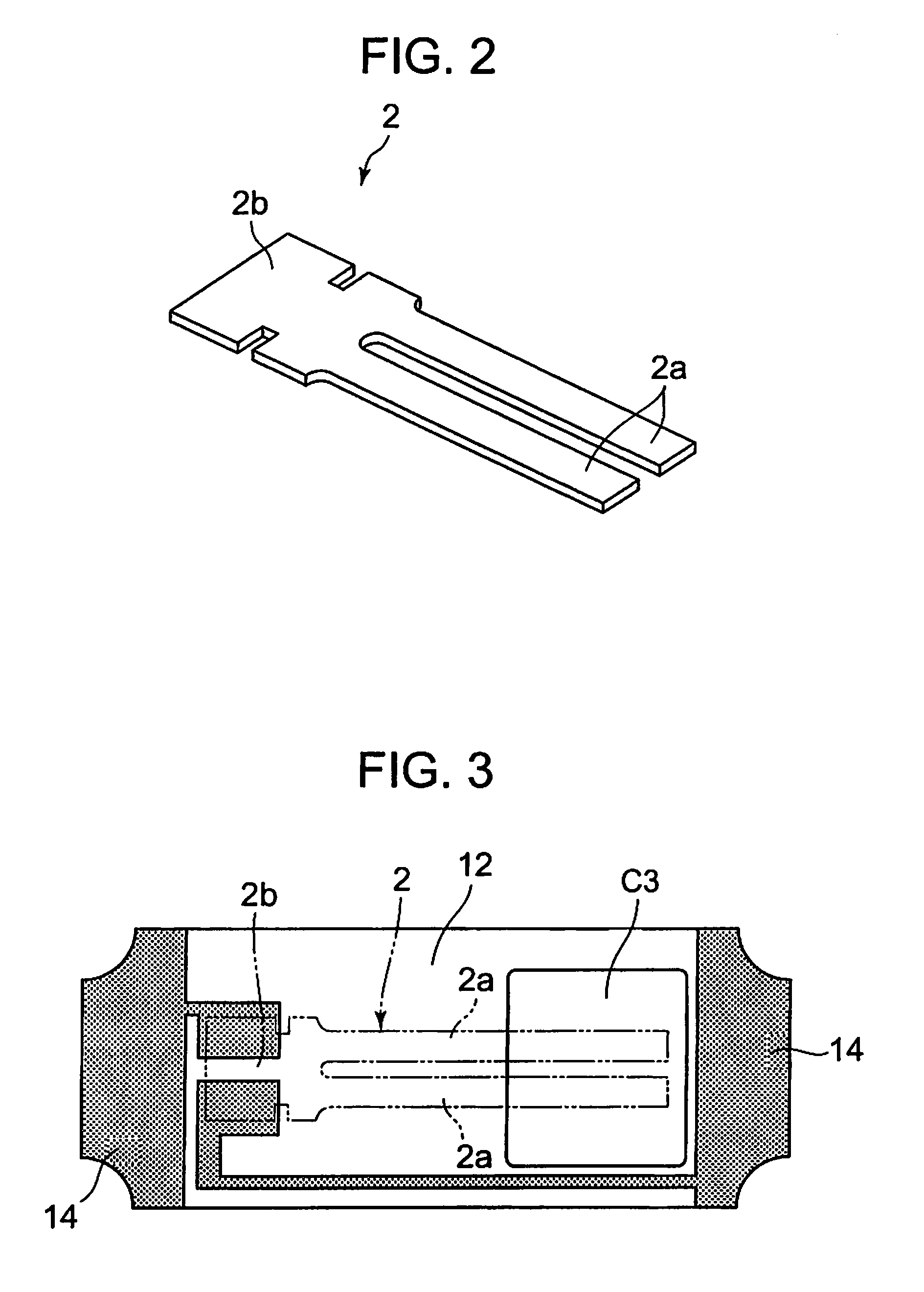
[0052]The piezoelectric vibrating strip 2 is a vibrating strip having a tuning fork formed of piezoelectric material such as crystal, lithium tantalite, or lithium niobate as shown in FIG. 2, and is configured to vibrate when a predetermined voltage is applied thereto. In other...


PUM

PropertyMeasurementUnit
Areaaaaaaaaaaa
Piezoelectricityaaaaaaaaaa

Abstract

There is There is provided a method of manufacturing a package 1 having a base substrate 10 and a lid substrate 20 bonded to each other and both formed of a glass base material; and a cavity C formed between the both substrates for storing an encapsulated object 2 in a state of being hermetically encapsulated, including: a depression forming step for forming a depression C1 for a cavity which defines the cavity when the both substrates are superimposed to each other on at least one of the both substrates; and a bonding step for superimposing the both substrates so as to store the encapsulated object in the depression and then bonding the both substrates to encapsulate the encapsulated object in the cavity, characterized in that in the depression forming step, printed layers 12 are laminated on an upper surface of a flat plate-shaped glass base material 11 in a frame shape in plan view by screen printing, and then the printed layers and the glass base material are baked at the same time to form the depression.

Description

RELATED APPLICATIONS[0001]This application is a continuation of PCT / JP2008 / 071570 filed on Nov. 27, 2008, which claims priority to Japanese Application No. JP2007-314751 filed on Dec. 5, 2007. The entire contents of these applications are incorporated herein by reference.TECHNICAL FIELD[0002]The present invention relates to a method of manufacturing a package having a cavity for hermetically sealing an encapsulated object, a package manufactured by the manufacturing method, an electronic device using the package, a piezoelectric vibrator, an oscillator having the piezoelectric vibrator, an electronic apparatus, and a radio clock.BACKGROUND ART[0003]In recent years, various electronic components, for example, a piezoelectric vibrator is used in a mobile phone set or a portable information terminal as a time source or a timing source of a control signal or the like. The piezoelectric vibrator of this type includes various types, and that employing a tip-mount system having a sealed co...

Claims


Application Information

Patent Timeline
IPC IPC(8): H04R17/00H01L41/053
CPCH03H3/02H03H9/1021Y10T29/42H03H2003/026H03H9/21
Inventor ARATAKE, KIYOSHIKAWADA, YASUO
Owner SII CRYSTAL TECH
Learn More