Single loop attemperation control

a control system and single loop technology, applied in steam engine plants, steam superheaters, steam regeneration, etc., can solve problems such as shortening the life cycle of control measures, adverse effects on steam turbines, and shortened life cycles, and affecting the operation of steam turbines downstream of hrsg

Active Publication Date: 2010-09-23
GENERAL ELECTRIC CO
View PDF14 Cites 22 Cited by
  • Summary
  • Abstract
  • Description
  • Claims
  • Application Information

AI Technical Summary

Problems solved by technology

If the outlet steam from the superheaters reaches high enough temperatures, the steam turbine, as well as other equipment downstream of the HRSG, may be adversely affected.
For instance, high cyclic thermal stress in the steam piping and steam turbine may eventually lead to shortened life cycles.
In some cases, due to excessive temperatures, control measures may trip the gas turbine and / or steam turbine.
This may result in a loss of power generation that may, in turn, impair plant revenues and operability.
Inadequately controlled steam temperatures may also lead to high cyclic thermal stress in the steam piping and steam turbine, affecting their useful life.
Unfortunately, these control systems often allow temperatures to overshoot during transient periods where, for instance, inlet temperatures into the superheaters increase rapidly.
Conversely, while trying to control high outlet steam temperatures, there are other potential adverse attemperation control effects.
There is a danger of causing the temperature to go too low resulting in subsaturated attempertor fluid flowing through the superheaters, interconnecting piping, or steam turbine.
Control stability problems can also use cyclic life of the steam system downstream of the attemperator as well as effect the life of the attemperation system valves, pumps, etc.
Unfortunately, this technique may not always work to control steam temperature overshoots during transient changes in the gas turbine output.
In addition, this technique may often require a great deal of tuning in order to verify satisfactory operation during all potential transients.
Regarding the overshoot problem with the non-model-based technique, as the temperature of the exhaust gas from the gas turbine increases, the temperature of the steam exiting the finishing high-pressure superheater may not only increase beyond the set point temperature, but may continue to overshoot a maximum allowable temperature even after the temperature of the exhaust gas begins to decrease.
This overshoot problem may be due in part to the presence of significant thermal lag caused by the mass of metal used in the finishing high-pressure superheater.
This overshoot problem may also become more acute when the gas turbine exhaust temperature changes rapidly.
Due to the presence of a cascade control structure the control tuning is not easy as the changes in one controller affect the performance of the other.
Due to a competitive market and tight commissioning schedules such a controller can end up being less than optimally tuned, thus adversely affecting the long term performance of the whole system.

Method used


Image

  • Single loop attemperation control
  • Single loop attemperation control
  • Single loop attemperation control

Examples


Embodiment Construction

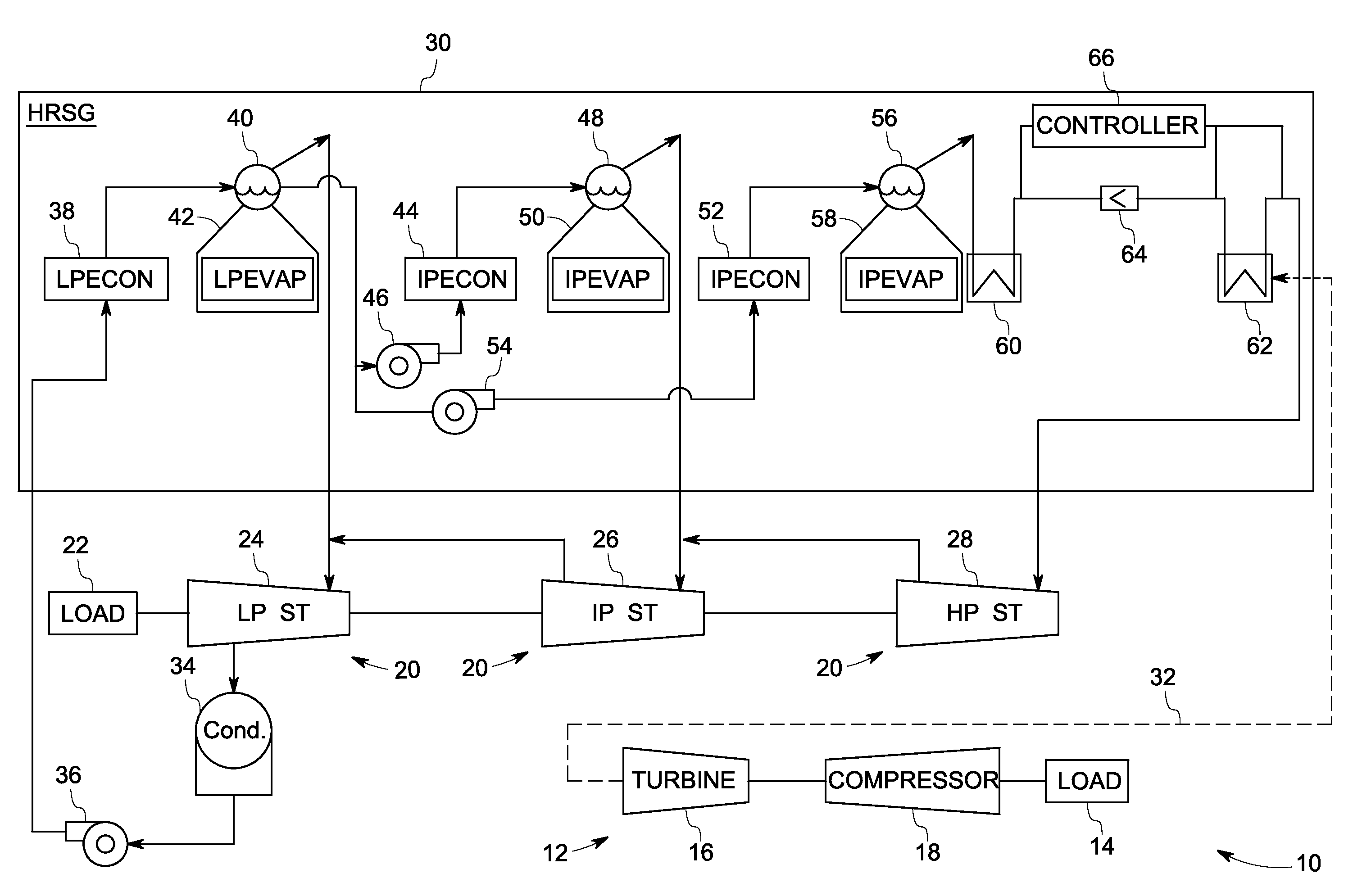
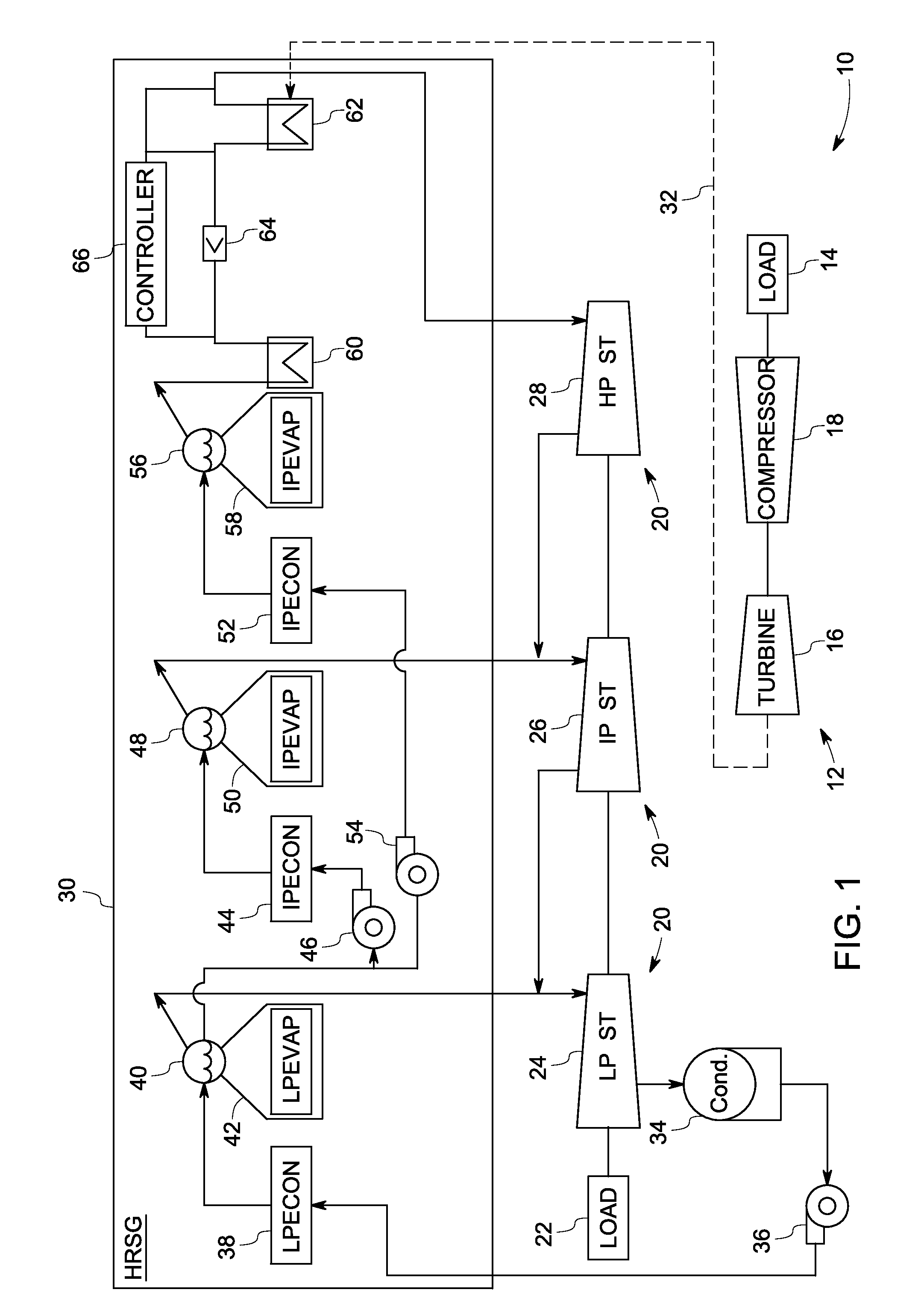
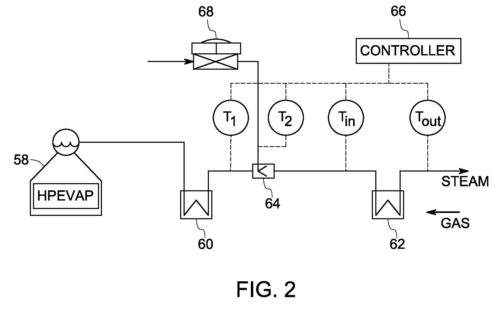
[0016]The present techniques are generally directed to a control system and method for controlling operation of an inter-stage attemperation system upstream of the finishing superheater, further controlling the outlet temperature from the finishing superheater. The control system includes a feed-forward and a feedback control and employs valve characteristics calculation for converting attemperating flow to valve demand for controlling temperature. In particular, embodiments of the control system may determine if attemperation is desired based on whether the outlet temperature of steam from the finishing superheater exceeds a set point temperature as well as whether the inlet temperature of steam into the finishing superheater approaches or is less than the saturation temperature of steam.

[0017]When introducing elements of various embodiments of the present invention, the articles “a,”“an,”“the,” and “said” are intended to mean that there are one or more of the elements. The terms “...


PUM


Abstract

A heat recovery steam generation system is provided. The heat recovery steam generation system includes at least one superheater in a steam path for receiving a steam flow and configured to produce a superheated steam flow. The system also includes an inter-stage attemperator for injecting an attemperation fluid into the steam path. The system further includes a control valve coupled to the inter-stage attemperator. The control valve is configured to control flow of attemperation fluid to the inter stage attemperator. The system also includes a controller coupled to the control valve and the inter-stage attemperator. The controller further includes a feedforward controller and a trimming feedback controller. The feedforward controller is configured to determine a desired amount of flow of the attemperation fluid and the trimming feedback controller is configured to compensate for inaccuracies in the determined amount of flow of the attemperation fluid to determine a net desired amount of flow of attemperation fluid through the control valve into an inlet of the inter-stage attemperator based upon an outlet temperature of steam from the superheater. The controller also determines a control valve demand based upon the flow to valve characteristics. The controller further manipulates the control valve of the inter-stage attemperator, and injects the desired amount of attemeration flow via the inter-stage attemperator to perform attemperation upstream of an inlet into the superheater.

Description

BACKGROUND[0001]The present invention relates generally to control systems for controlling temperatures. More specifically, the invention relates to a temperature control of steam in relation to inter-stage attemperation, which may be used in heat recovery steam generation (HRSG) systems in combined cycle power generation applications.[0002]HRSG systems may produce steam with very high outlet temperatures. In particular, HRSG systems may include superheaters through which steam may be superheated before being used by a steam turbine. If the outlet steam from the superheaters reaches high enough temperatures, the steam turbine, as well as other equipment downstream of the HRSG, may be adversely affected. For instance, high cyclic thermal stress in the steam piping and steam turbine may eventually lead to shortened life cycles. In some cases, due to excessive temperatures, control measures may trip the gas turbine and / or steam turbine. This may result in a loss of power generation tha...

Claims


Application Information

Patent Timeline
Patent Type & Authority Applications(United States)
IPC IPC(8): F01K13/02F01K3/26F01K19/00
CPCF22G5/12
Inventor KUMAR, RAJEEVAMINTO, KARL DEANSEELY, WILLIAM FORRESTERCARBERG, WILLIAM GEORGEPOLUKORT, PETER PAUL
Owner GENERAL ELECTRIC CO
Why Eureka
Try Eureka