Collector modules for devices for removing particles from a gas

a technology of collecting modules and gas, applied in the direction of transportable electrostatic units, electric supply techniques, magnetic separation, etc., can solve the problems of shortening the effective “creeping distance”, affecting the efficiency of the operation, and the risk of damaging the arc between the components at different potentials, etc., to achieve the effect of enhancing long-term reliability, reducing time and cost, and reducing the risk of damag

Active Publication Date: 2010-09-23
GRACE CREATION INVESTMENT LTD
View PDF34 Cites 17 Cited by
  • Summary
  • Abstract
  • Description
  • Claims
  • Application Information

AI Technical Summary

Benefits of technology

[0006]The embodiments of the present invention comprise collector modules which are particularly useful with devices for removing particles from a gas, and will be described herein in the context of household air cleaners. The illustrated embodiments are designed to reduce the time and cost of manufacture while enhancing the long term reliability, allow the use of more vigorous as well as convenient cleaning methods such as using a dishwasher, and enable relatively compact structures. As used herein, the term “module” refers to a subassembly of components, including at least one driver electrode, which is useful in devices for removing particles from gases.
[0007]According to one embodiment of the present invention, the use of epoxy insulating material in a collector module comprising at least one and preferably a plurality of driver electrodes is significantly reduced. In this embodiment of the present invention, electrical communication is established between at least one and preferably a plurality of insulated driver plates and at least one other conductor and / or a source of electrical potential using a conductive electrical connector, such as a conductive screw, eyelet or similar fastener, which passes through a hole in or along an edge of the driver plate(s) and conductor. The portions of the driver plate(s) and other conductors in which electrical communication(s) are established are physically biased toward each other, preferably by the conductive connector, or alternatively by another biasing member. If a non-fastener type conductive electrical connector is used, the driver electrode and the other conductive part can be biased together by a separate element, e.g. a clamp. If this collector module comprises only one driver, the other conductor may be a contact which is connected to the voltage source.
[0008]According to another embodiment of the present invention, the number of electrical contact points between a source of electrical potential and insulated driver plates in a collector module is significantly reduced by forming a plurality of insulated driver plates from a single, bent, insulated conductive plate. In this embodiment, a single insulated conductive plate serves as a plurality of driver electrode plates positioned on opposite sides of at least one, and preferably a plurality of, collector electrodes, e.g. collector plates. The single conductive plate can be bent or formed to serve as a plurality of driver electrode plates.
[0009]According to another embodiment of the present invention, a shielded high voltage generating circuit, collector electrodes and driver electrodes and, optionally one or more emitters, are integrated into in a single, machine washable, collector module which is easily removable from a collector module support and which can withstand repeated cleanings with cleaning fluids such as dishwasher detergents. Since the high voltage output(s) of the high voltage generating circuit are shielded as part of the collector module, the connections between the collector module and the collector module support can be limited to low voltage power, ground and control inputs, thereby avoiding the need for a high voltage input to the collector module. This embodiment of the present invention facilitates easy and regular cleaning of the collector module. This embodiment also eliminates the need for additional safety features which are typically required in order to shield a user from high voltage shocks when removing a collector module from an air cleaner for cleaning.

Problems solved by technology

The use of such high potentials creates the risk of damaging arcing between components at different potentials and necessitates additional steps in the manufacture and maintenance of the device.
While a proper insulation will adhere well to the driver plates, problems tend to occur in the electrical contacts joining the insulated drivers to their source of electrical potential.
Additionally, particles initially entrained in the air, e.g. dust and dirt, particularly when combined with high humidity, will collect on one or more of the plates and can shorten the effective “creeping distance”.
Electrical shorts and arcing can result and cause irreversible damage to the device.
However, many good insulators such as polyester and Teflon do not bond very well with many epoxy materials.
As the epoxy and the insulator are subjected to mechanical shocks and / or temperature variations, over time small cracks tend to develop in the bonds.
Water can be trapped in those cracks during washing processes.
When the cracks propagate, the water will short the shielded contact.
If the distance between the openings of the cracks and the collector plates is less than the distance required to avoid arcing, i.e. the arcing distance to the collector plates, arcing will occur and the collector module can be irreversibly damaged.
Even when the distance between the openings of the cracks and the collector plates is longer than the arcing distance to the collector plates, their creeping distances will usually be rather small and do not provide stable operation since the accumulation of some moist dirt / particles can lead to arcing across the driver electrodes and collector plates.
Moreover, the bond of the epoxy to the insulator will often degrade very quickly if it is subjected to dishwasher treatment.

Method used


Image

  • Collector modules for devices for removing particles from a gas
  • Collector modules for devices for removing particles from a gas
  • Collector modules for devices for removing particles from a gas

Examples


Embodiment Construction

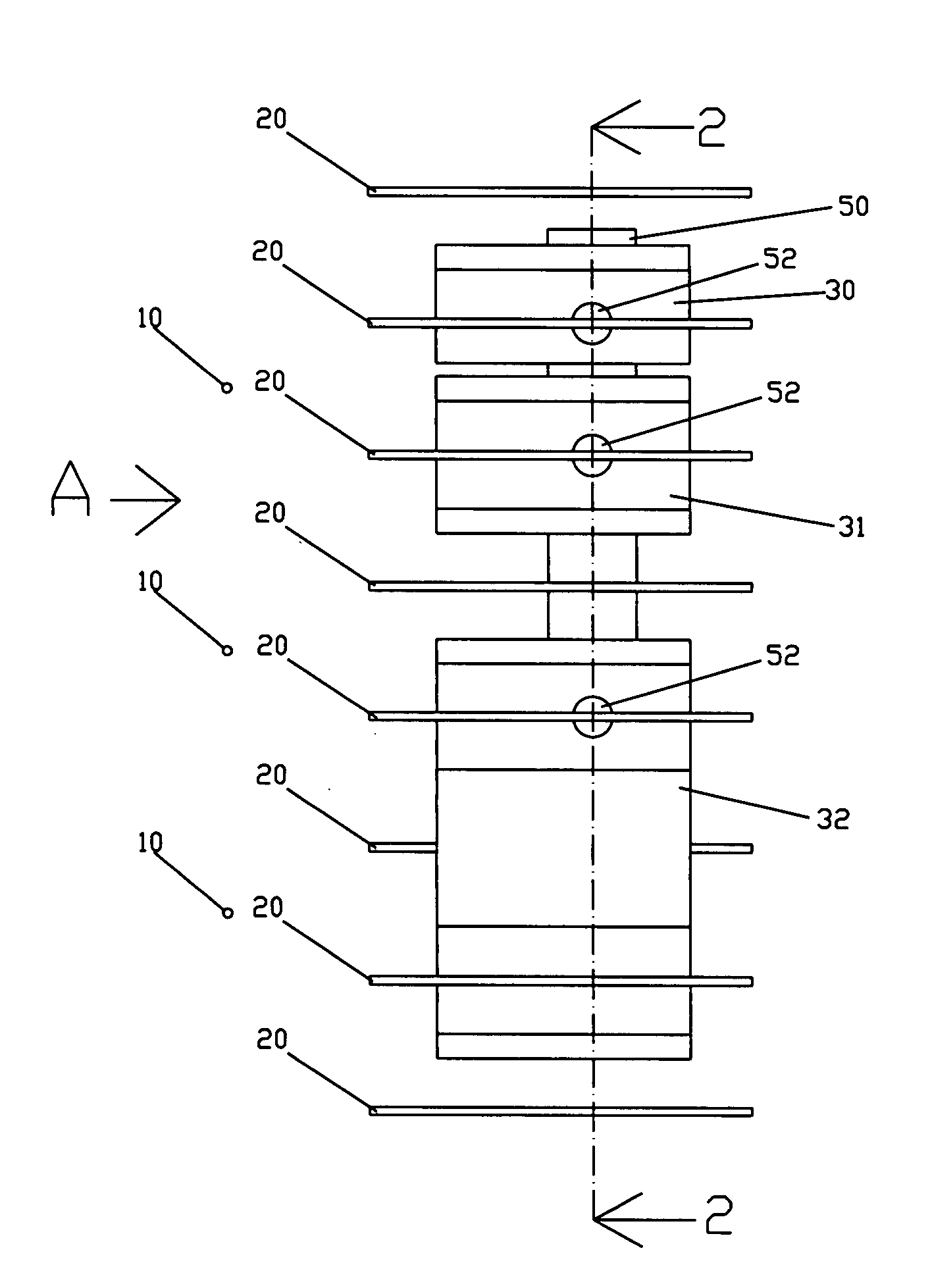
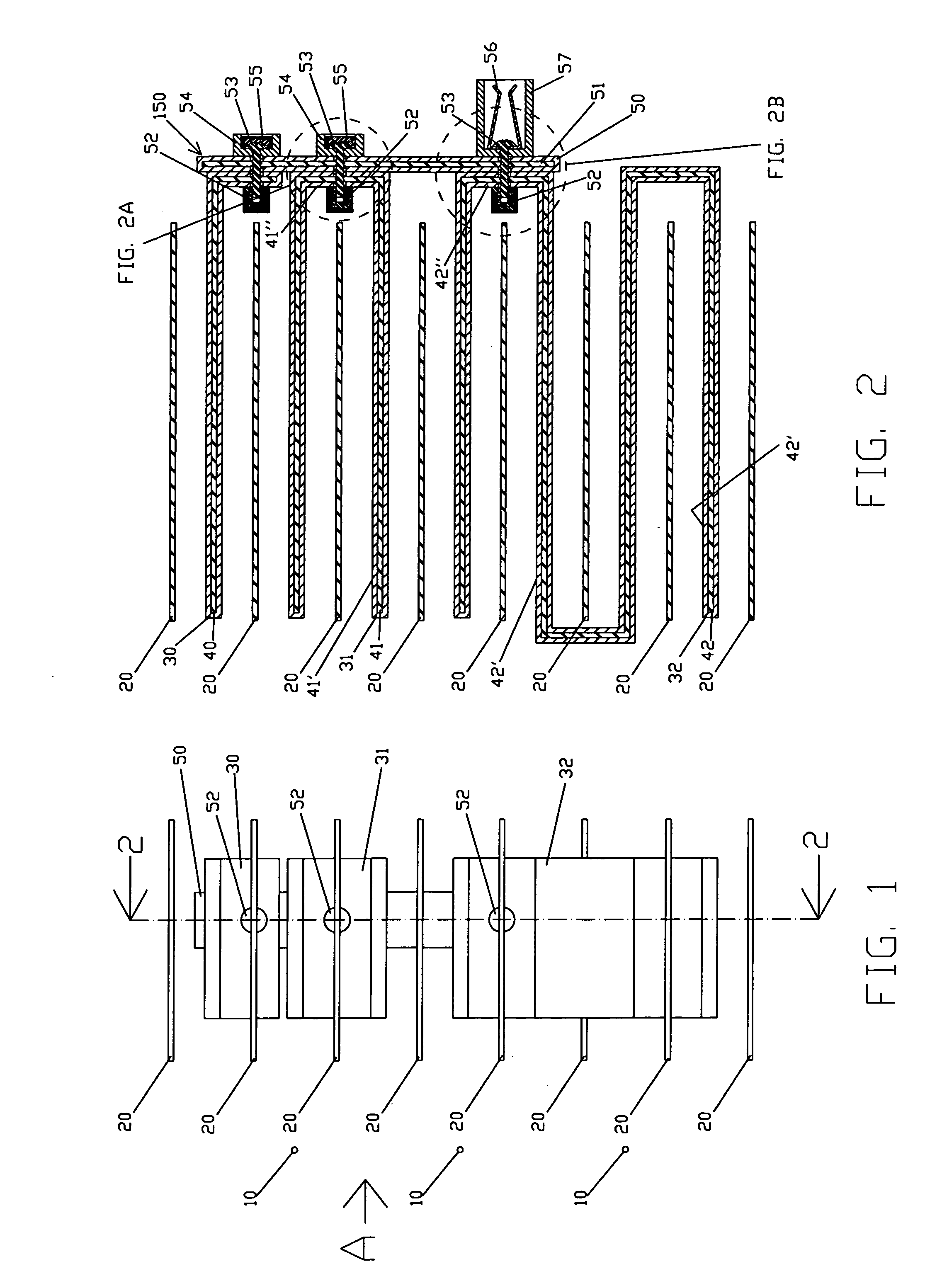
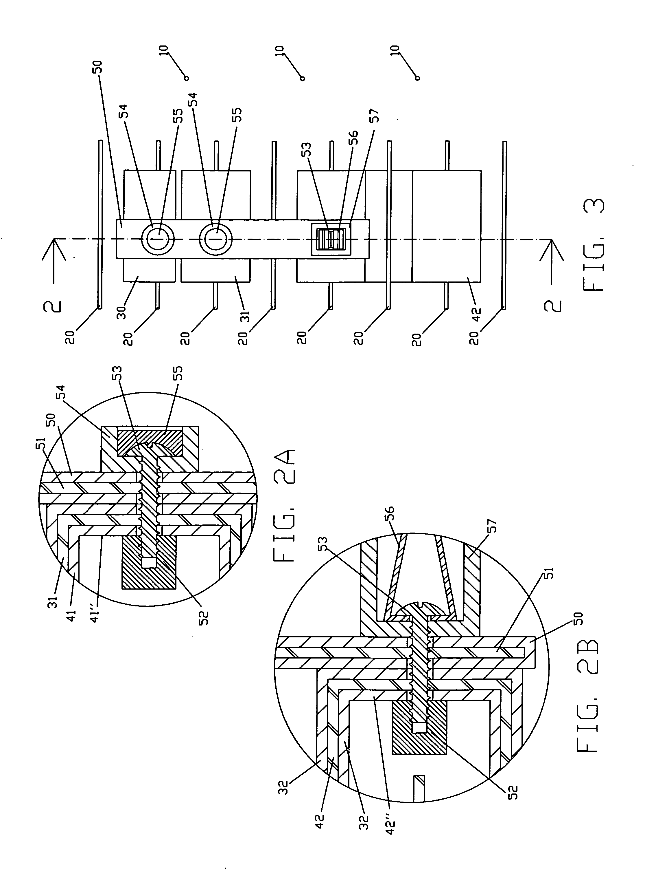
[0032]FIGS. 1 to 3 illustrate a collector module of the present invention embodying two aspects of the present invention which minimize the number of electrical connections to the insulated driver plates and minimize the use of epoxy. This illustrated collector module comprises eight collector electrodes 20 which are positioned with seven driver plates 40 positioned between them. Supporting structure and other components of the air cleaner are not shown in these figures. One or more emitters 10 can be included in the collector modules of this embodiment of the present invention, but in this illustrated embodiment, the illustrated emitters 10 are not part of the collector module. In this illustrated embodiment, the air flow is in the direction of arrow A shown in FIG. 1. The device can also be oriented in a different direction, e.g. for a vertical air flow, if desired.

[0033]As best shown in FIG. 2, four insulated driver electrode plates 42′ are formed by bending a single, insulated, ...


PUM


Abstract

Devices for removing particles for a gas utilizing electrostatic precipitation comprising collector modules with fewer electrical connections, which facilitate cleaning, and / or eliminate the need for high voltage connections between a removable collector module and a collector module support. Driver electrode modules provide electrical connection between an insulated driver electrode and a source of electrical potential or between insulated driver electrodes and at least one other conductor through a hole in or on some edge on the driver electrodes. A biasing force is provided and a conductive element serves as a conductor between the driver electrode(s) and the other conductors. A plurality of insulated driver electrodes, e.g. plates, are formed with a single, conductive plate or from a plurality of electrically joined conductive plates which are coated with insulation and then bent. An electrically-shielded, high voltage generating circuit is integrated with a readily removable collector module to eliminate the need for high voltage connections between the removable collector module and the collector module support, while enhancing the device's durability and allowing cleaning with cleaning fluid and / or dishwasher detergent.

Description

RELATED APPLICATION DATA[0001]This application claims the benefit of Provisional Patent Application Ser. No. 61 / 210,551 filed on Mar. 20, 2009.[0002]The present invention relates to devices for removing particles from gases comprising electrostatic precipitators, e.g. household air cleaners, and to collector modules and improved electrical connectors for such devices.BACKGROUND[0003]Some electrostatic air cleaners utilize an electrical potential difference between spaced collector electrode plates and driver electrode plates to facilitate particle deposition on the collector plates. For efficient collection of particles from air, a high potential, usually 10 kV to 30 kV, is applied between the collector plates and insulated driver plates. The use of such high potentials creates the risk of damaging arcing between components at different potentials and necessitates additional steps in the manufacture and maintenance of the device. For example, the contact points, i.e. the portions wh...

Claims


Application Information

Patent Timeline
Patent Type & Authority Applications(United States)
IPC IPC(8): B03C3/45B03C3/68B03C3/00
CPCB03C3/08B03C3/12B03C3/32B03C2201/28B03C3/68B03C3/70B03C3/86B03C3/368
Inventor CHAN, SIK LEUNG
Owner GRACE CREATION INVESTMENT LTD
Why Eureka
Try Eureka