Valve Seat Insert for a Split-Cycle Engine

a technology of valve seat insert and internal combustion engine, which is applied in the direction of valve arrangement, combustion engine, machine/engine, etc., can solve the problems of affecting the performance of the valve seat insert, the valve seat insert can be very frequently impacted, and the valve seat insert can be dislodged from the recess

Inactive Publication Date: 2010-09-23
SKADERI GRUP LLC
View PDF18 Cites 12 Cited by
  • Summary
  • Abstract
  • Description
  • Claims
  • Application Information

AI Technical Summary

Benefits of technology

[0025]The present invention offers advantages over the prior art by providing an improved valve seat insert. The improved valve seat insert is capable of staying in place within a recess of a cylinder head while providing a valve seat for a fast actuating, outwardly opening valve with a short axial height, which operates under high pressure conditions. The present invention further provides an innovative method and valve seat insert tool for installing an improved valve seat insert into the recess of a cylinder head.
[0026]The improved valve seat insert innovatively combines a cylindrical interference fit section and a threaded section. The interference fit section aligns the valve seat and can prevent rotation of the valve seat insert. The threaded section prevents axial movement of the valve seat insert.
[0029]A further embodiment of the present invention may include an apparatus comprising a cylinder head disposed on a cylinder. The apparatus may further include a valve seat insert, disposed in a recess of the cylinder head, and including a valve seat insert body, a passage extending through the body that fluid can flow through, a valve seat disposed in the passage, and an outer periphery of the body disposed within the cylinder head and including an interference section and a threaded section. The apparatus may further include an outwardly opening valve having an open position wherein the valve is located off of the valve seat and away from an interior of the cylinder, and a closed position wherein the valve abuts the valve seat. The valve may control fluid communication into or out of the cylinder through the passage by reciprocating between the open and closed positions such that the valve repeatedly impacts the valve seat in an axial direction toward the interior of the cylinder. The interference section may align the valve seat such that the valve seat is concentric with a center line axis of the valve. The threaded section may prevent axial movement of the valve seat insert toward the interior of the cylinder during the repeated impacts.

Problems solved by technology

Problematically, outwardly opening valves create the opposite effect.
This impact tends to push the valve seat insert towards the interior of the cylinder head and out of the recess in the cylinder head, which could potentially dislodge the valve seat insert from the recess of the cylinder head.
The impact problem is exacerbated in internal combustion engines with fast valve actuation rates where the valve velocity is greater than 6 meters / second.
This is because the impacts against the valve seat insert can occur very frequently, with relatively high valve seating velocities and / or with greater force.
The impact problem is also exacerbated in internal combustion engines with high pressure fluid in contact with an outwardly opening valve or valve seat insert.
The impact problem is further exacerbated in applications that require valve seat inserts with a short axial height.
Problematically, a large radial interference would likely lead to component failure.
Accordingly, the prior art methodology of designing a radial interference fit between valve seat and cylinder head is not feasible on its own.
However, the risk of disassembly is real even for the threaded joint, because the impacts at valve closing would generate vibrations potentially capable, in time, of unscrewing the seat.
Problematically however, in engine valve seat applications, it is not possible to have long components.
This is because lengthy valve seats would interfere with the packaging of other features and components in the cylinder head assembly.
In addition, use of outwardly opening valves raises assembly problems when used with conventional valve seat inserts.
As discussed above, fast actuation rates, outwardly opening valves, pressure on a valve seat insert, and / or a short axial height requirement can be problematic with conventional valve seat inserts.

Method used


Image

  • Valve Seat Insert for a Split-Cycle Engine
  • Valve Seat Insert for a Split-Cycle Engine
  • Valve Seat Insert for a Split-Cycle Engine

Examples


Embodiment Construction

Split-Cycle Engine

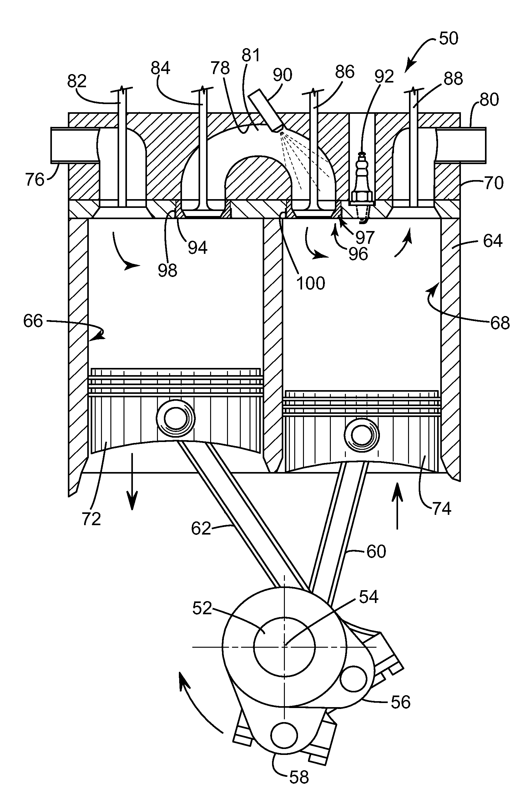
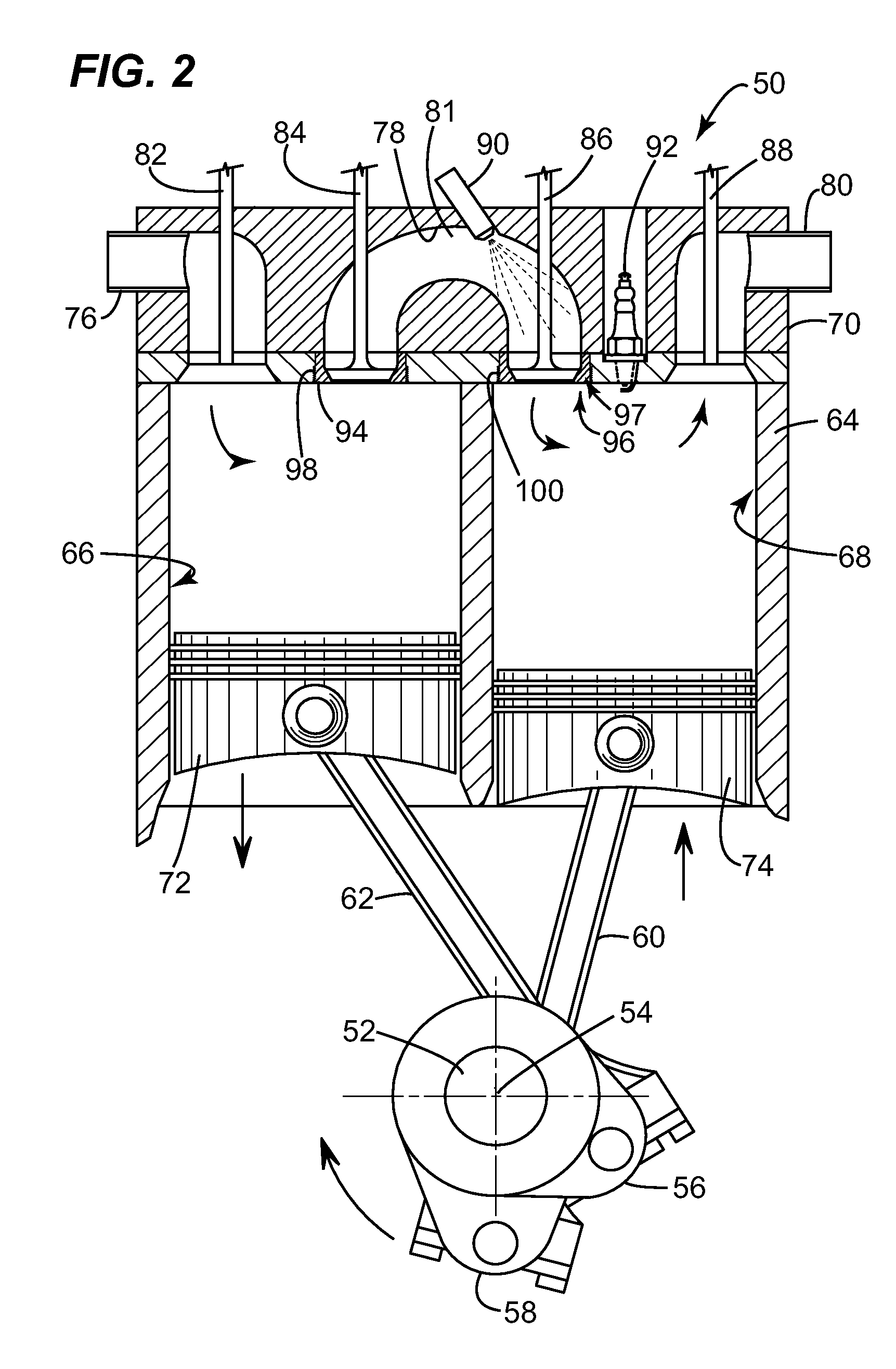
[0042]Referring now to FIG. 2 in detail, numeral 50 generally indicates a diagrammatic representation of a split-cycle engine according to the invention. Engine 50 includes a crankshaft 52 rotatable about a crankshaft axis 54 in a clockwise direction as shown in the drawing. The crankshaft 52 includes adjacent angularly displaced leading and following crank throws 56, 58, connected to connecting rods 60, 62, respectively.

[0043]Engine 50 further includes a cylinder block 64 defining a pair of adjacent cylinders, in particular a compression cylinder 66 and an expansion cylinder 68 closed by a cylinder head 70 at one end of the cylinders opposite the crankshaft 54.

[0044]A compression piston 72 is received in compression cylinder 66 and is connected to the connecting rod 62 for reciprocation of the piston between top dead center (TDC) and bottom dead center (BDC) positions. An expansion piston 74 is received in expansion cylinder 68 and is connected to the connecting r...


PUM

PropertyMeasurementUnit
crank angleaaaaaaaaaa
velocityaaaaaaaaaa

Abstract

The present invention provides an improved valve seat insert, particularly for split-cycle engines with outwardly opening crossover valves. The improved valve seat insert combines an interference fit section with a threaded section. The interference fit section aligns a valve seat and can prevent rotation of the valve seat insert. The threaded section prevents axial movement of the valve seat insert.

Description

TECHNICAL FIELD[0001]The present invention generally relates to a valve seat insert for use with outwardly opening valves. More specifically, the present invention relates to a valve seat insert in a split-cycle internal combustion engine for one or more valves that open away from the interior of the cylinders and a method of installing such a valve seat insert.BACKGROUND OF THE INVENTION[0002]For purposes of clarity, the term “conventional engine” as used in the present application refers to an internal combustion engine wherein all four strokes of the well known Otto or Diesel cycle (the intake, compression, expansion and exhaust strokes) are contained in each piston / cylinder combination of the engine. Each stroke requires one half revolution of the crankshaft (180 degrees crank angle (CA)), and two full revolutions of the crankshaft (720 degrees CA) are required to complete the entire Otto or Diesel cycle in each cylinder of a conventional engine.[0003]In a conventional internal ...

Claims


Application Information

Patent Timeline
Patent Type & Authority Applications(United States)
IPC IPC(8): F02B33/22F16K1/42
CPCB23P11/025F01L3/22F16K1/422F02B33/22F01L2003/258
Inventor MELDOLESI, RICCARDOPERKINS, ANTHONY STUARTLACY, CLIVE BARRINGTONWESTMORELAND, BARRY EDWARDMEGEL, MARC CHRISTOPHER
Owner SKADERI GRUP LLC
Why Eureka
Try Eureka