Modular scalable coolant distribution unit

a distribution unit and modular technology, applied in the field of modular, scalable, coolant distribution units, can solve the problems of inability to meet the demand for cooling, inability to reach the maximum load, unnecessary up-front capital costs and inefficiencies, etc., to achieve low cost, reduce up-front costs, and reduce heat load. the effect of large variation of heat load

Inactive Publication Date: 2010-09-23
VETTE TECH
View PDF14 Cites 84 Cited by
  • Summary
  • Abstract
  • Description
  • Claims
  • Application Information

AI Technical Summary

Benefits of technology

[0011]The modularity of the system reduces up front costs and permits installation of only components initially needed. It supports any size or tier level data center and supports an air and liquid cooling solution. The system handles workload variations. While rack population density may cause heat load to vary from under one to over thirty kilowatts, workload variations for a given rack can similarly cause a large heat load variation. For example, processors running complex simulations will be at full power,

Problems solved by technology

Computer room air conditioning (CRAC) systems are increasingly unable to meet the demand for cooling.
However, this maximum load may not be reached for months or years as facility requirements start small and grow with business demand.
This leads to unnecessary up-front capital costs and inefficiencies.
Cooling s

Method used


Image

  • Modular scalable coolant distribution unit
  • Modular scalable coolant distribution unit
  • Modular scalable coolant distribution unit

Examples


first embodiment

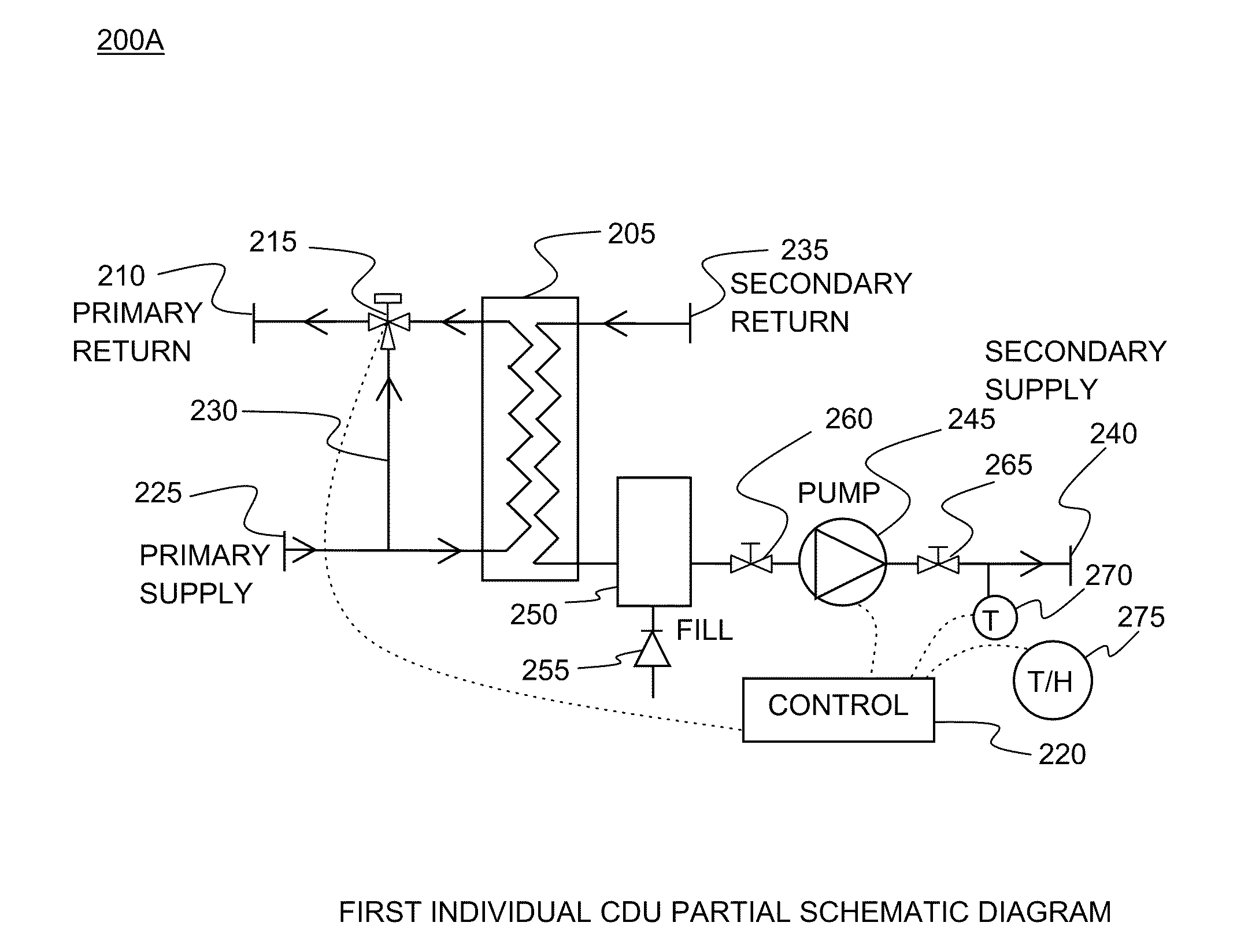
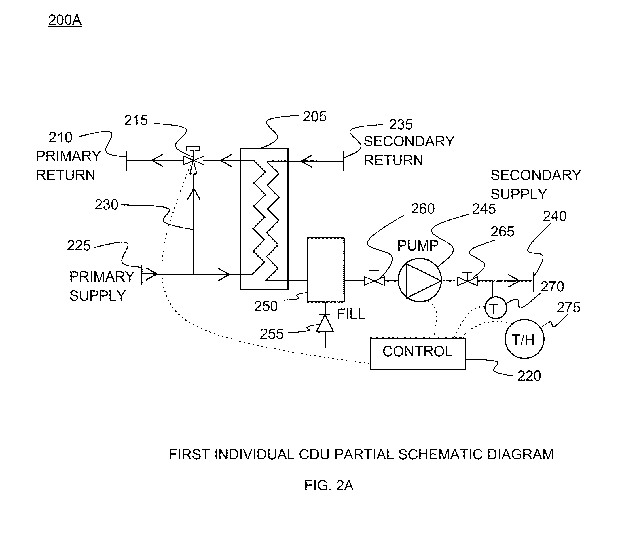
[0057]FIG. 2A illustrates a partial schematic of a scalable modular CDU 200A with heat exchanger 205 including primary return 210 controlled by 3-way valve 215. In embodiments, heat exchanger 205 is a brazed plate heat exchanger. Valve 215 is controlled by control unit 220. Primary supply 225 feeds heat exchanger 205. Valve 215 controls flow between primary supply 225, primary return 210 (through primary coolant loop bypass line 230) and heat exchanger 205. Secondary return 235 is in fluid connection with heat exchanger 205. Secondary supply 240 includes pump 245. Pump 245 is connected to control unit 220. Between pump 245 and heat exchanger 205 is expansion tank 250. Connected to expansion tank 250 is automatic fill system 255. Between expansion tank 250 and pump 245 is first secondary supply valve 260. After pump 245 in secondary supply 240 is second secondary supply valve 265. After valve 265 in secondary supply 240 is coolant temperature sensor 270. Coolant temperature sensor 27...

second embodiment

[0058]FIG. 2B illustrates a partial schematic of a scalable modular CDU 200B with heat exchanger 205 including primary return 210 controlled by control valves 276A & B. In embodiments, control valve control valve 276B is redundant. In embodiments, heat exchanger 205 is a stainless steel brazed plate heat exchanger. Valves 276A & B are controlled by control unit 220. Primary supply 225 feeds heat exchanger 205. Bypass valve 277 controls flow between primary supply 225 and primary return 210. Secondary return 235 is in fluid connection with heat exchanger 205. In embodiments, secondary return 235 comprises internal manifolds or flexible tails, coupling 282 and air eliminator 283. Secondary supply 240 includes pumps 245A & B. In embodiments, pump 245B is redundant. Pumps 245A & B are connected to control unit 220 via speed control 284. Between pumps 245A & B and heat exchanger 205 is auto fill expansion tank 250. Connected to auto fill expansion tank 250 is automatic fill system compri...

embodiment 300

[0059]FIG. 3 is a perspective diagram of a modular scalable CDU cooling system overview embodiment 300 depicting multiple CDUs 305. CDUs 305 are connected by primary loop 310 to cooling source such as facility water 315. CDUs 305 are connected by secondary loop 320 to one or more equipment heat exchangers 325. As non-limiting examples, heat exchangers 325 can be equipment rack rear door liquid to air heat exchangers, room air heat exchangers, direct component liquid cooling heat exchangers, or any combination.


PUM


Abstract

An equipment cooling system and method employing modular scalable coolant distribution units that interface with each other to provide liquid cooling for computer data centers. The coolant distribution unit (CDU) permits the use of elevated water temperatures without increasing the load on the computer room air conditioning. A control unit processes environment data to control pump and valve components supporting redundancy and multiple primary and secondary coolant loops.

Description

RELATED APPLICATIONS[0001]This application claims the benefit of U.S. Provisional Application No. 61 / 161,538, filed Mar. 19, 2009; this application is herein incorporated in its entirety by reference.FIELD OF THE INVENTION[0002]The invention relates to a system and method for incrementally controlling cooling of heat generating equipment, and more particularly, to a modular, scalable, coolant distribution unit (CDU). Embodiments support multiple primary and secondary coolant loops.BACKGROUND OF THE INVENTION[0003]Equipment racks and the data centers populated with them have generated more heat as their processing power increases. Computer room air conditioning (CRAC) systems are increasingly unable to meet the demand for cooling. Typical CRAC systems have been extensions of building air conditioning units used to cool office spaces. As data center cooling needs have increased, more specialized systems have appeared to meet cooling needs.[0004]Some of today's cooling needs can be met...

Claims


Application Information

Patent Timeline
IPC IPC(8): F28F27/00
CPCH05K7/20836H05K7/2079
Inventor NOVOTNY, SHLOMO D.MENOCHE, JOHN P.RODEN, DAVID W.
Owner VETTE TECH
Why Eureka
Try Eureka