Maintaining catalyst activity for converting a hydrocarbon feed

a technology of hydrocarbon feed and catalyst activity, which is applied in the field of fluid catalytic cracking, can solve the problems of unnecessarily regenerating, affecting catalyst performance, and reducing the yield of propylene, so as to maximize the yield

Inactive Publication Date: 2010-09-23
UOP LLC
View PDF28 Cites 11 Cited by
  • Summary
  • Abstract
  • Description
  • Claims
  • Application Information

AI Technical Summary

Benefits of technology

[0006]One exemplary embodiment can be a process for fluid catalytic cracking. The process can include withdrawing a catalyst f

Problems solved by technology

In such systems, the regeneration may have an adverse affect on catalyst performance.
Hence, the common regeneration o

Method used


Image

  • Maintaining catalyst activity for converting a hydrocarbon feed
  • Maintaining catalyst activity for converting a hydrocarbon feed
  • Maintaining catalyst activity for converting a hydrocarbon feed

Examples


Embodiment Construction

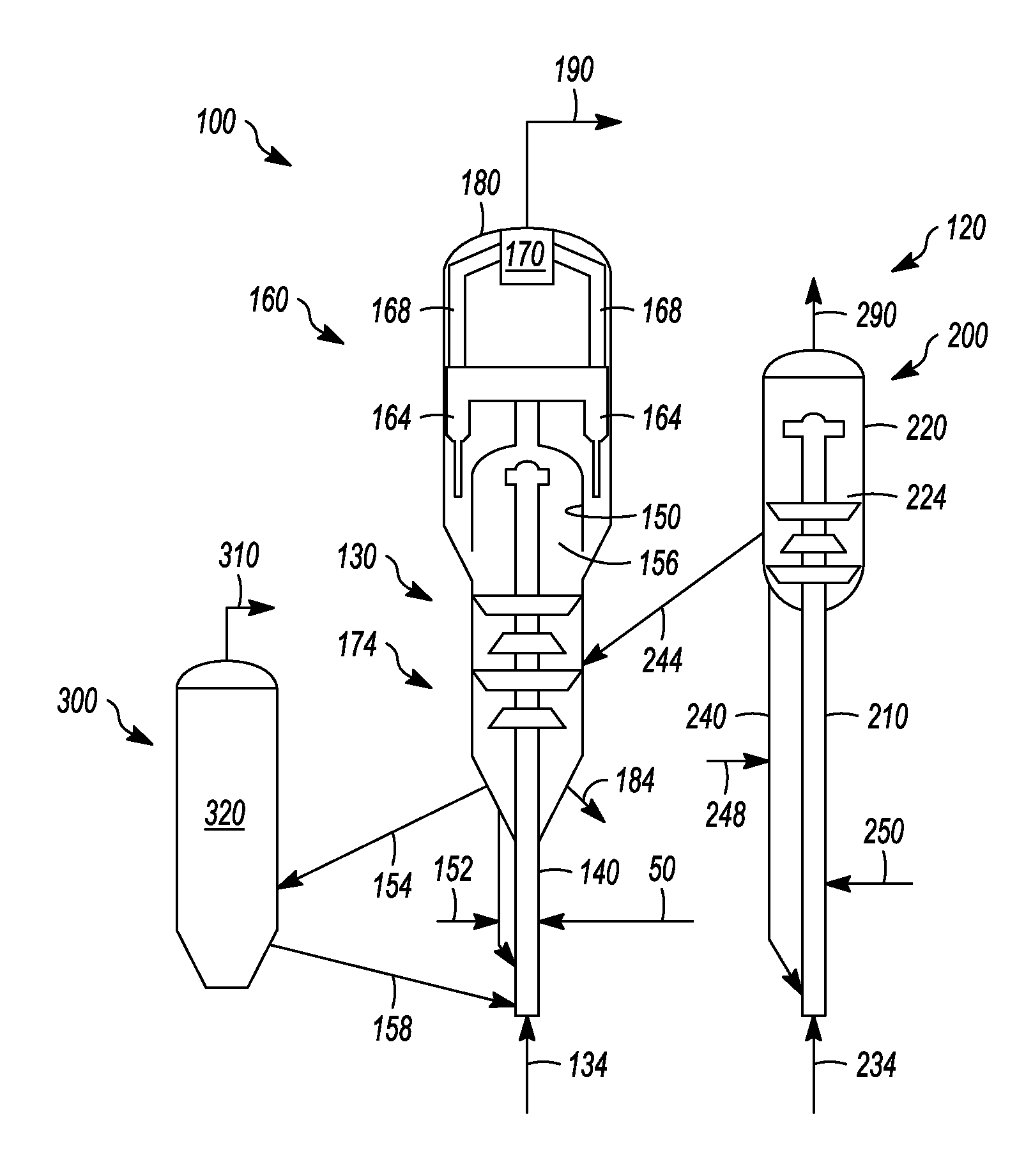
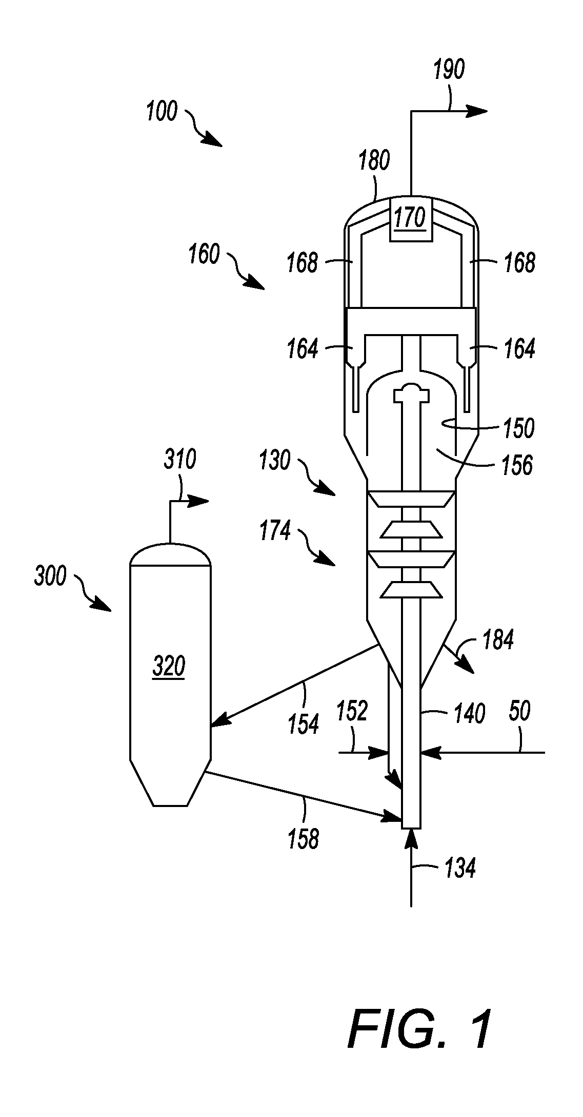
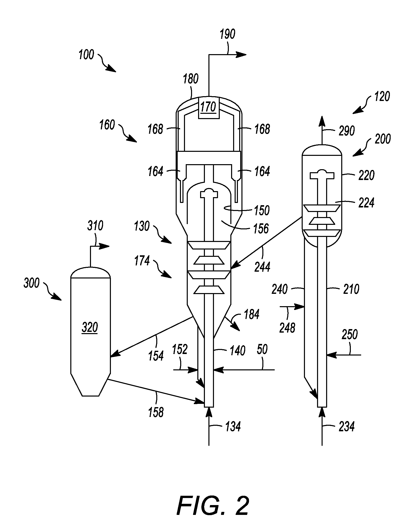
[0020]Referring to FIG. 1, an exemplary fluid catalytic cracking system and / or unit 100 can usually include a reaction zone or a first reaction zone 130 and a regeneration zone 300. In this exemplary embodiment, a catalyst section can include the first reaction zone 130 and a regeneration zone 300. Generally, the first reaction zone 130 can include a first riser 140 terminating in a first reaction vessel 150 defining a volume 156. Although a riser reactor is depicted, it should be understood that any suitable reactor or reaction vessel can be utilized, such as a fluidized bed reactor or a fixed bed reactor. The first riser 140 can receive a feed 50 that can have a boiling point range of about 180- about 800° C. Typically, the feed 50 can be at least one of a gas oil, a vacuum gas oil, an atmospheric gas oil, and an atmospheric residue. Alternatively, the feed 50 can be at least one of a heavy cycle oil and a slurry oil. Generally, the feed 50 can be a fresh feed, or receive a recycl...


PUM


Abstract

One exemplary embodiment can be a process for fluid catalytic cracking. The process can include withdrawing a catalyst from a reaction vessel to replace a catalyst inventory over a period of about 10- about 35 days for maximizing propylene yield.

Description

FIELD OF THE INVENTION[0001]This invention generally relates to fluid catalytic cracking, and more preferably maintaining catalyst activity in such a system and / or process.DESCRIPTION OF THE RELATED ART[0002]Catalytic cracking can create a variety of products from larger hydrocarbons. Often, a feed of a heavier hydrocarbon, such as a vacuum gas oil, is provided to a catalytic cracking reactor, such as a fluid catalytic cracking reactor. Various products may be produced from such a system, including a gasoline product and / or light product such as propylene and / or ethylene.[0003]In such systems, a single reactor or a dual reactor can be utilized. Although additional capital costs may be incurred by using a dual reactor system, one of the reactors can be operated to tailor conditions for maximizing products, such as light olefins including propylene and / or ethylene.[0004]It can be desirable to provide fresh catalyst to maintain product yields. Typically, fresh catalyst replaces lost ca...

Claims


Application Information

Patent Timeline
IPC IPC(8): C10G51/04B01J8/26
CPCC10G11/05C10G51/06C10G51/026
Inventor UPSON, LAWRENCE L.HEDRICK, BRIAN W.COUCH, KEITH ALLEN
Owner UOP LLC
Why Eureka
Try Eureka