Production of propylene in a fluid catalytic cracking unit

a technology of propylene and hydrocarbon feedstock, which is applied in the direction of hydrocarbon preparation catalysts, hydrocarbon oil treatment products, organic chemistry, etc., can solve the problems of not teaching any method, unable to meet the incremental demand of propylene, and conventional steam cracking units, etc., to achieve the effect of maximizing the propylene yield

Active Publication Date: 2018-02-22
INDIAN OIL CORPORATION
View PDF3 Cites 8 Cited by
  • Summary
  • Abstract
  • Description
  • Claims
  • Application Information

AI Technical Summary

Benefits of technology

[0017]It is the primary objective of the invention to provide a modified process and apparatus to further maximize the propylene yield.

Problems solved by technology

The conventional steam cracking units, which are more energy intensive, cannot meet the incremental demand of propylene as its propylene to ethylene ratio is low.
However, this prior art doesn't teach cracking of C4 hydrocarbons to C3 olefins.
However, the prior art does not teach any method that is directed specifically to conversion of C4 hydrocarbons to C3 olefins.
However, this prior art doesn't provide any means for achieving optimum temperature and catalyst activity which facilitates maximum propylene yield.
But it is seen that beyond certain temperature, the propylene production doesn't improve.

Method used


Image

  • Production of propylene in a fluid catalytic cracking unit
  • Production of propylene in a fluid catalytic cracking unit
  • Production of propylene in a fluid catalytic cracking unit

Examples


example

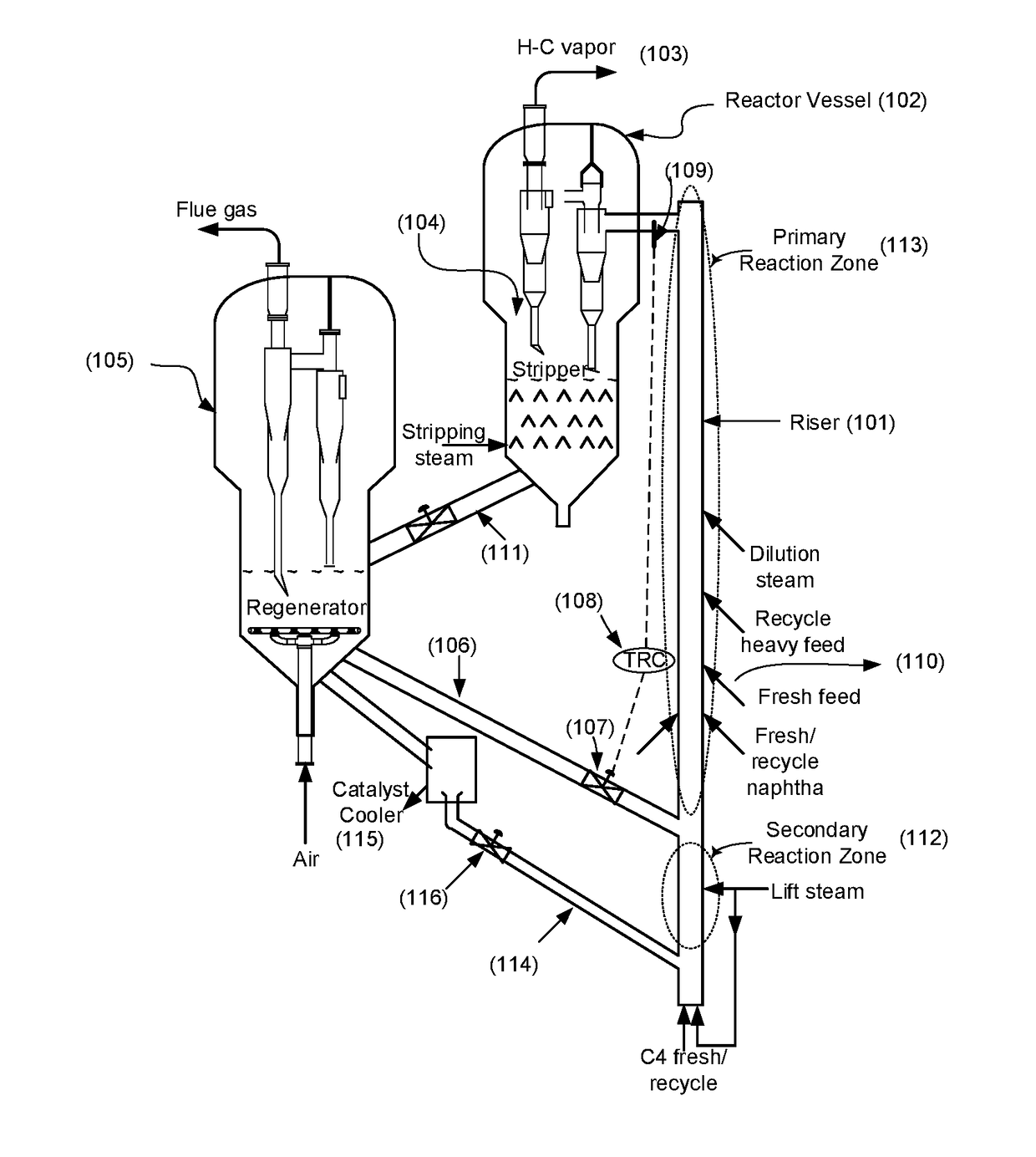
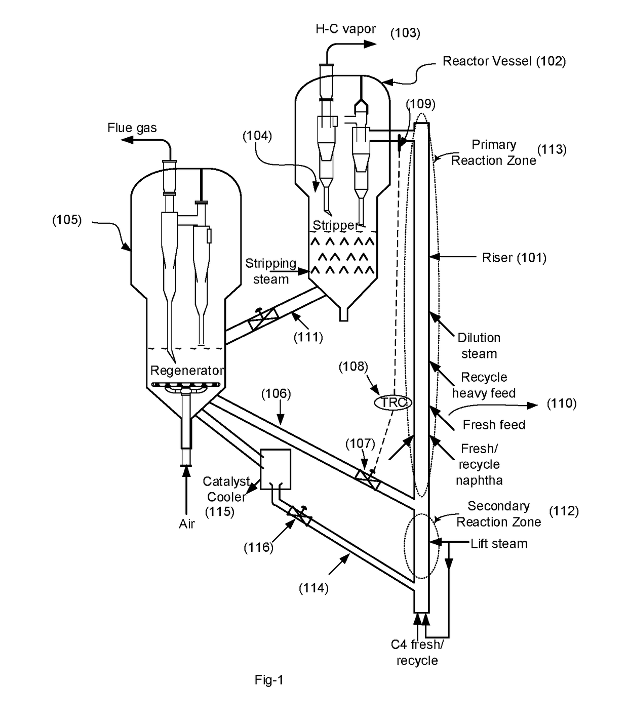
[0062]This example demonstrates the improvement in propylene yield in FCCU obtained through cracking of the product C4 stream generated out of cracking of residue feed in the riser using a residue feed having 4.4 wt % conradson carbon residue (CCR) and 941 kg / m3 density. The example given in this section is for illustration purpose only and don't construe to the claims as mentioned in subsequent section.

[0063]The data shown in this example have been generated through preliminary engineering calculations based on experimental data from micro—reactor and pilot plant. Base case data is at a reaction temperature of 580° C. and without any C4 cracking. The catalyst used is a mixture of FCC catalyst having average particle size of 80 microns based on USY zeolite and an additive based on pentasil zeolite having silica to alumina molar ratio of 30. The catalyst was hydrothermally deactivated at 810° C. for 5 hrs. The composition of C4 stream used in the study is given in Table-I.

TABLE IComp...


PUM

PropertyMeasurementUnit
temperatureaaaaaaaaaa

Abstract

A process and apparatus for catalytic cracking of hydrocarbon feedstock employing circulating fluidized bed reactor-regenerator configuration for maximizing the yield of propylene (C3 olefin) is disclosed. The apparatus comprises two reaction zones operating under different temperature and weight hourly space velocity (WHSV), one primary zone for cracking of hydrocarbon feedstock and other as secondary zone for cracking of C4 fraction produced from the cracking of hydrocarbon feedstock in the primary reaction zone, optionally admixed with C4 stream from external source. Two dedicated conduits equipped with valves for control of catalyst flow rate are provided to supply the hot catalyst from a common catalyst regeneration zone wherein the catalyst flowing though conduit connected to the secondary reaction zone is cooled employing a heat exchanging device. The lower temperature achieved in secondary reaction zone on account of exchange of heat along with lower weight hourly space velocity (WHSV) selectively promotes oligomerisation of C4 fraction before being cracked to produce C3 olefin in the subsequent portion of the reaction zone (primary).

Description

FIELD OF THE INVENTION[0001]The present invention relates to a process and apparatus for catalytic cracking of hydrocarbon feedstock. More particularly, this invention covers process for catalytic cracking of hydrocarbon by employing circulating fluidized bed reactor-regenerator configuration for maximizing the yield of propylene (C3 olefin).BACKGROUND OF THE INVENTION[0002]Fluid Catalytic Cracking (FCC) is the most important conversion process used in petroleum refineries. It is widely used to convert the high-boiling, high-molecular weight hydrocarbon fractions of petroleum crude oils to more valuable gasoline, olefinic gases, and other products. Cracking of petroleum hydrocarbons was originally done by thermal cracking, which has been almost completely replaced by catalytic cracking because of its adaptability towards improved and selective cracking to produce high octane gasoline and valuable lighter olefinic gaseous products. This process also provides flexibility to be tuned t...

Claims


Application Information

Patent Timeline
Patent Type & Authority Applications(United States)
IPC IPC(8): C07C4/06C10G57/02
CPCC07C4/06C10G57/02C07C2529/08C10G2300/4081C07C2529/80C10G2400/20C07C2529/40C10G11/18C10G11/187C10G11/00C10G11/182C10G11/185
Inventor BHUYAN, MANOJ KUMARKUMARAN, SATHEESH VETTERKUNNELBHATTACHARYYA, DEBASISKHAN, SHOEB HUSSAINDE, BIDYUTPANDE, SUDHIR KUMAR
Owner INDIAN OIL CORPORATION
Why Eureka
Try Eureka