Battery pack, and battery system

a battery system and battery pack technology, applied in the manufacture of secondary batteries, electrochemical generators, transportation and packaging, etc., can solve the problems of secondary batteries becoming unsafe states, unnecessary power loss increases, and expected life shortened, so as to reduce unnecessary power loss, and reduce the variation in the state of charge

Inactive Publication Date: 2010-09-23
PANASONIC CORP
View PDF3 Cites 33 Cited by
  • Summary
  • Abstract
  • Description
  • Claims
  • Application Information

AI Technical Summary

Benefits of technology

[0005]The present invention was devised in view of the foregoing circumstances. Thus, an object of this invention is to provide a battery pack and a battery system capable of reducing unnecessary power loss upon reducing the variation in the state of charge that occurred between the respective secondary batteries in cases where an assembled battery in which a plurality of secondary batteries are connected in series is connected in parallel.
[0008]With the battery pack and battery system configured as described above, the first and second assembled batteries are connected in parallel when viewed from the charge terminal, and the first and second assembled batteries are connected in parallel when viewed from the discharge terminal. When charging the first assembled battery, the control unit turns OFF the first discharging path switch unit and the second charge switch unit so as to prohibit the charging current that was received by the charge terminal from being supplied to the second assembled battery. Subsequently, as a result of the control unit turning ON the first charge switch unit and all secondary batteries contained in the first assembled battery being charged until they are fully charged, the variation in the state of charge between the respective secondary batteries contained in the first assembled battery will decrease. Here, since the current supply to the second assembled battery is prohibited, it is possible to reduce the unnecessary power loss upon reducing the variation in the state of charge in the first assembled battery.
[0009]Moreover, when charging the second assembled battery, the control unit turns OFF the second discharging path switch unit and the first charge switch unit so as to prohibit the charging current that was received by the charge terminal from being supplied to the first assembled battery. Subsequently, as a result of the control unit turning ON the second charge switch unit and all secondary batteries contained in the second assembled battery being charged until they are fully charged, the variation in the state of charge between the respective secondary batteries contained in the second assembled battery will decrease. Here, since the current supply to the first assembled battery is prohibited, it is possible to reduce the unnecessary power loss upon reducing the variation in the state of charge in the second assembled battery.

Problems solved by technology

When using a rechargeable battery pack including a plurality of secondary batteries connected in series as described in Patent Document 1, it is generally known that variation will arise in the quantity of accumulated charge of the batteries while they are being used, and the continued use thereof may cause only certain secondary batteries to become an overcharged state or an overdischarged state, whereby the expected life may become shortened or the secondary batteries may become an unsafe state.
Thus, there was an inconvenience in that unnecessary power loss will increase.Patent Document 1: Japanese Patent Application Laid-open No.

Method used


Image

  • Battery pack, and battery system
  • Battery pack, and battery system
  • Battery pack, and battery system

Examples


Embodiment Construction

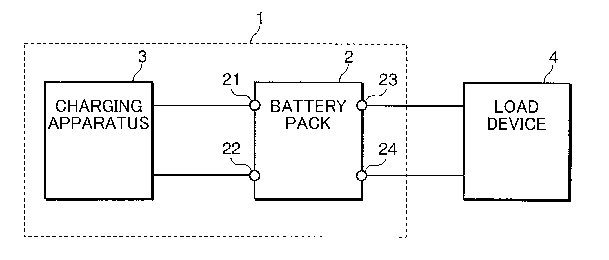
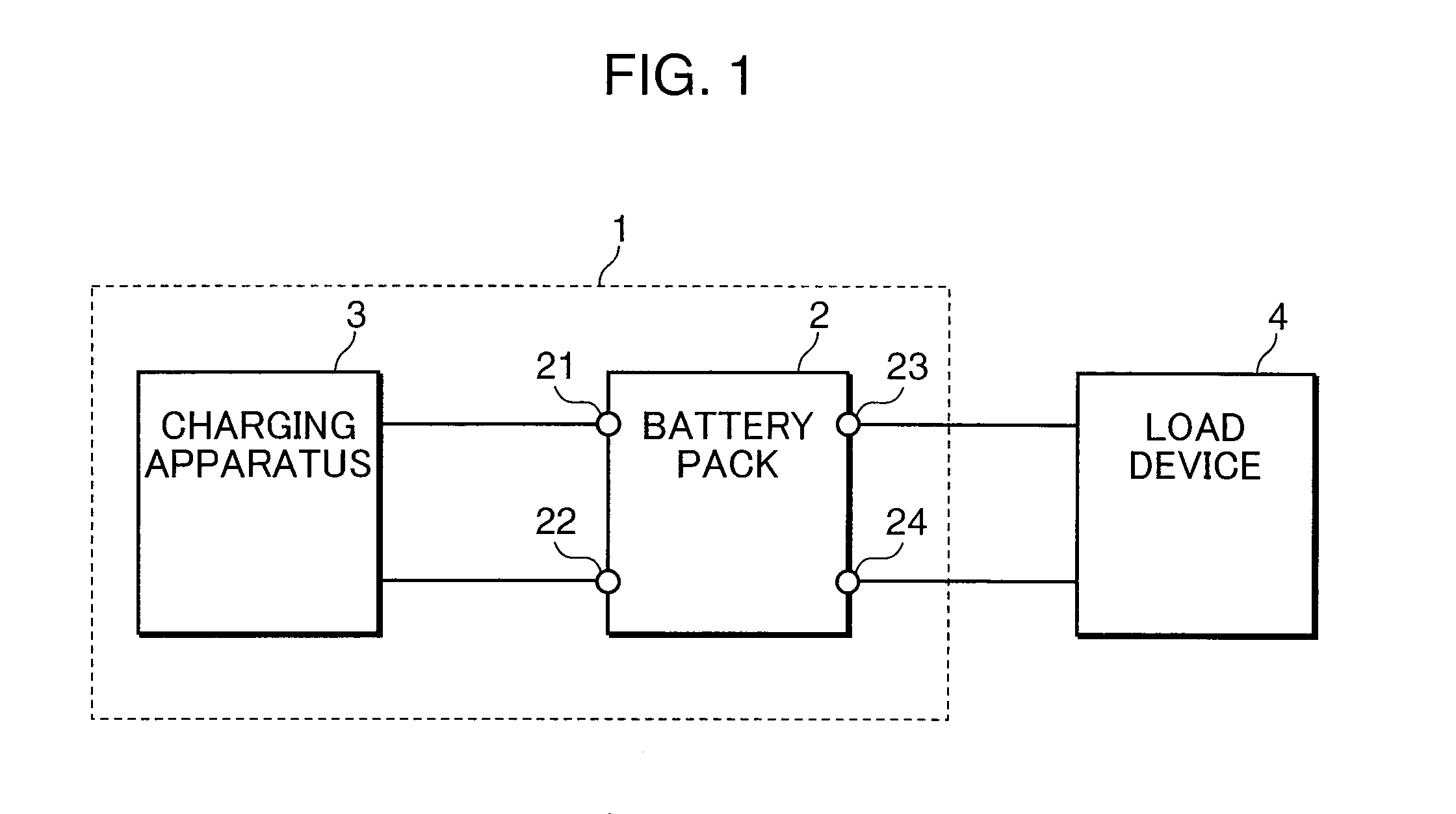
[0015]An embodiment of the present invention is now explained with reference to the attached drawings. Incidentally, configurations that are given the same reference numeral in the respective drawings mean that they are of the same configuration, and the explanation thereof is omitted. FIG. 1 is a block diagram showing an example of the configuration of the battery system according to an embodiment of the present invention. The battery system 1 shown in FIG. 1 comprises a battery pack 2, and a charging apparatus 3 (charging current supply unit).

[0016]The charging apparatus 3 is a power circuit for outputting a charging current for charging the battery pack 2. The battery pack 2 comprises connecting terminals 21, 22, 23, 24. The connecting terminals 21, 22 are charge terminals for receiving the charging current output from the charging apparatus 3, and are connected to the charging apparatus 3. The connecting terminals 23, 24 are discharge terminals for supplying the discharging curr...


PUM


Abstract

An object of the present invention is to provide a battery pack and a battery system capable of reducing unnecessary power loss upon reducing the variation in the state of charge that has occurred between a plurality of secondary batteries in an assembled battery in which the secondary batteries are connected in series-parallel. The battery pack and the battery system include a switching element Q11 for opening / closing the charging path of a battery pack B1, a switching element Q12 for opening / closing the discharging path of the battery pack B1, a switching element Q21 for opening / closing the charging path of a battery pack B2, and a switching element Q22 for opening / closing the discharging path of the battery pack B2. When the battery pack B1 is charged, the switching elements Q12, Q21 are turned OFF and the switching element Q11 is turned ON until the secondary batteries B11, B12 are fully charged. When the battery pack B2 is charged, the switching elements Q22, Q11 are turned OFF and the switching element Q21 is turned ON until the secondary batteries B21, B22 are fully charged.

Description

TECHNICAL FIELD [0001]The present invention relates to a battery pack in which a plurality of secondary batteries are connected in parallel, and a battery system.BACKGROUND ART [0002]When using a rechargeable battery pack including a plurality of secondary batteries connected in series as described in Patent Document 1, it is generally known that variation will arise in the quantity of accumulated charge of the batteries while they are being used, and the continued use thereof may cause only certain secondary batteries to become an overcharged state or an overdischarged state, whereby the expected life may become shortened or the secondary batteries may become an unsafe state. Thus, in order to resolve the variation in the state of charge (charging capacity) of the respective secondary batteries, a control method is known where charging is performed until the secondary battery with the smallest quantity of accumulated charge is fully charged and intentionally causing the other secon...

Claims


Application Information

Patent Timeline
Patent Type & Authority Applications(United States)
IPC IPC(8): H02J7/00H02J7/02
CPCH01M10/0413H01M10/0445H01M10/441Y02T10/7055H02J7/0016H02J7/0018H02J7/0054H01M10/46H02J7/342Y02E60/10Y02T10/70
Inventor MAEGAWA, KAZUYA
Owner PANASONIC CORP
Why Eureka
Try Eureka