Resistively heated small planar filament

a technology of resistively heated and filament, applied in the field of filaments, can solve the problem of less performance variability between devices, and achieve the effects of improving the accuracy of filament placement, and being easy to handle during manufacturing

Inactive Publication Date: 2010-09-23
MOXTEK INC
View PDF101 Cites 36 Cited by
  • Summary
  • Abstract
  • Description
  • Claims
  • Application Information

AI Technical Summary

Benefits of technology

[0006]It has been recognized that it would be advantageous to provide a filament which is easier to handle during manufacturing, resulting in more precise and repeatable placement of the filament. Increased precision of filament placement results in less performance variability between devices using these filaments. In addition, it has been recognized that it would be advantageous to provide a filament that maintains its shape during use and which is less susceptible to filament failures. In addition, it has been recognized that it would be advantageous to provide a smaller and mor

Problems solved by technology

Increased precision of filament placement results in less pe

Method used


Image

  • Resistively heated small planar filament
  • Resistively heated small planar filament
  • Resistively heated small planar filament

Examples


Embodiment Construction

[0024]Reference will now be made to the exemplary embodiments illustrated in the drawings, and specific language will be used herein to describe the same It will nevertheless be understood that no limitation of the scope of the invention is thereby intended. Alterations and further modifications of the inventive features illustrated herein, and additional applications of the principles of the inventions as illustrated herein, which would occur to one skilled in the relevant art and having possession of this disclosure, are to be considered within the scope of the invention.

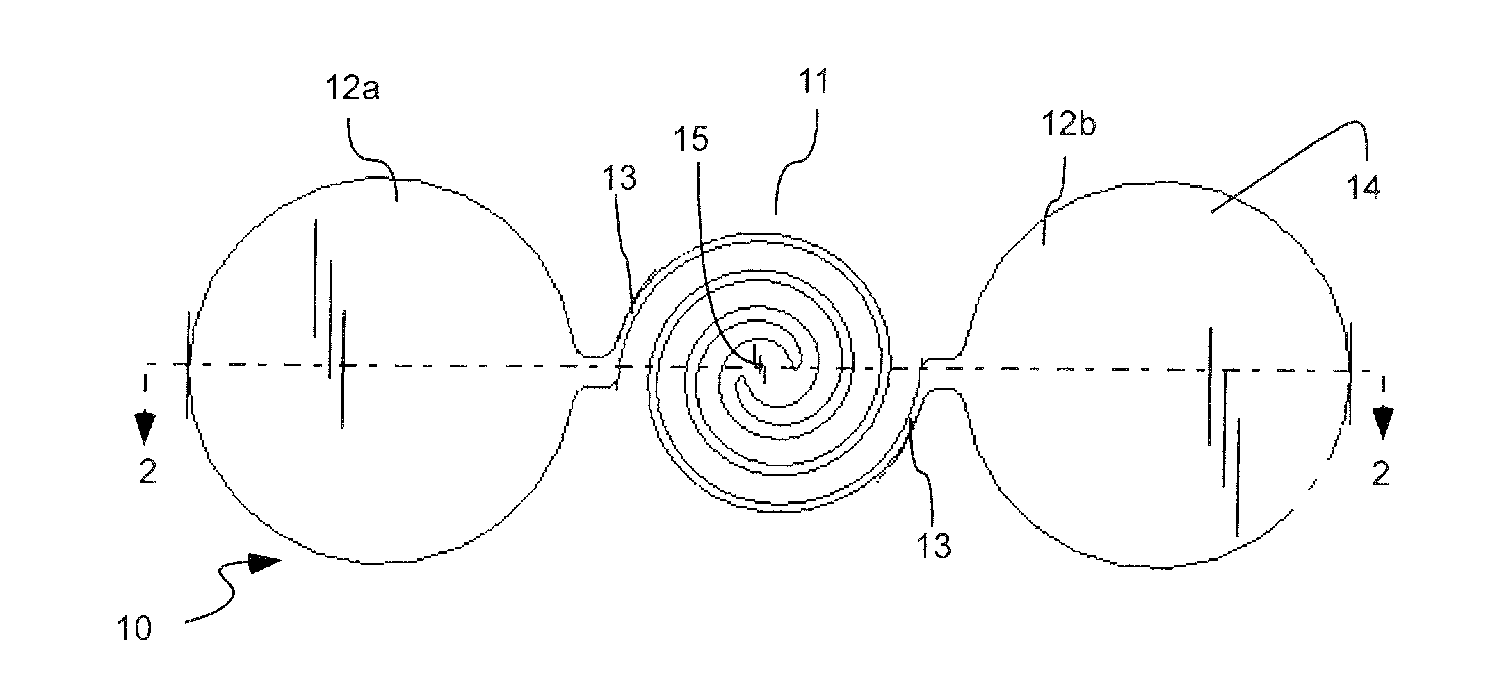
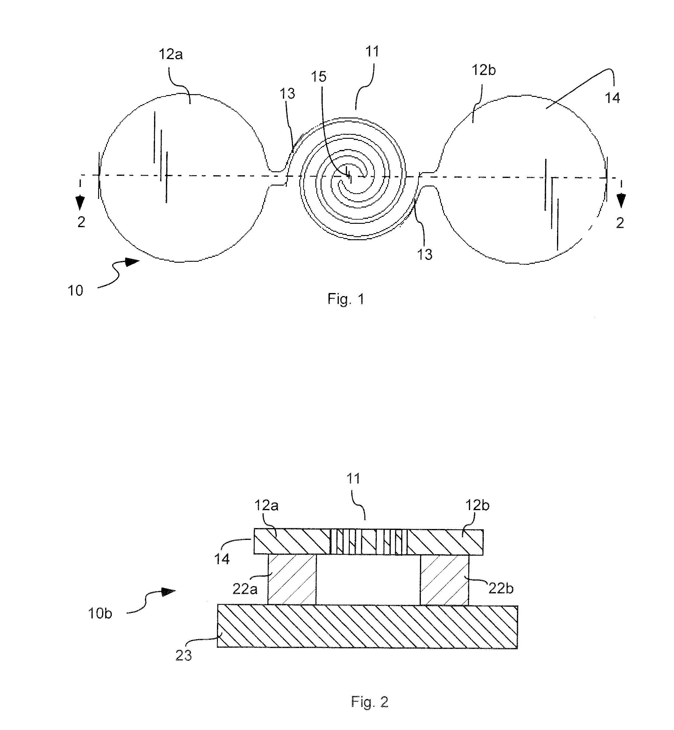
[0025]Referring to FIG. 1, a planar filament 10 in accordance with an exemplary embodiment of the present invention is shown. Two bond pads 12a and 12b are connected by a filament 11. The filament 11 can be sized and shaped to heat or otherwise emit electrons. The filament can include a material that is electrically conductive and configured to heat or otherwise emit electrons. Refractory materials such as tungste...


PUM

PropertyMeasurementUnit
Lengthaaaaaaaaaa
Electrical resistanceaaaaaaaaaa
Currentaaaaaaaaaa

Abstract

A planar filament comprising two bonding pads and a non-linear filament connected between the two bonding pads. The filament may be wider in the center to increase filament life. The planar filament may be mounted on a substrate for easier handling and placement. Voltage can be used to create an electrical current through the filament, and can result in the emission of electrons from the filament. The planar filament can be utilized in an x-ray tube.

Description

FIELD OF THE INVENTION[0001]The present invention relates to filaments used for electron emission or production of light.BACKGROUND[0002]Filaments are used to produce light and electrons. For example, in an x-ray tube, an alternating current heats a wire filament formed in a coiled cylindrical or helical loop. Due to the high temperature of the filament, and due to a large bias voltage between the filament and an anode, electrons are emitted from the filament and accelerated towards the anode. These electrons form an electron beam. The location where the electron beam impinges on the anode is called the “electron spot”. It is often desirable that this spot be circular with a very small diameter. It is also often desirable that this spot be in the same location on the anode in every x-ray tube that is manufactured.[0003]The shape and placement of the filament in the x-ray tube affects the shape of the spot. Some filaments are very small, especially in portable x-ray tubes. Placing su...

Claims


Application Information

Patent Timeline
IPC IPC(8): B32B3/10
CPCH01J1/16H01J1/18H01J35/06Y10T428/24802H01J2201/2867H01K1/14H01J2201/2853H01J35/064
Inventor CORNABY, STERLING W.BARD, ERIK C.
Owner MOXTEK INC
Why Eureka
Try Eureka