Crimping Tool

a technology of crimping tool and crimping die, which is applied in the direction of stripping off devices, basic electric elements, electrical equipment, etc., can solve the problems of work piece breaking free from the crimping contour, and achieve the reduction of the geometrical moment of inertia, the effect of avoiding the deformation of the crimping contour, and reducing the force required for removing the work piece from the crimping die halves

Inactive Publication Date: 2010-09-30
WEZAG - WERKZEUGFAB
View PDF23 Cites 4 Cited by
  • Summary
  • Abstract
  • Description
  • Claims
  • Application Information

AI Technical Summary

Benefits of technology

[0011]For crimping die halves according to the prior art, the person with skill in the art tried to build the crimping die half with its crimping contour as stiff and hard as possible in order to avoid deformations of the crimping contour during the crimping process. These deformations of the crimping contour were generally undesired due to the fact that such deformations have the result that at the end of the crimping process the produced contour of the work piece deviates from the desired contour. Surprisingly, the present invention leaves the aforementioned route of the person with skill in the art by building the crimping die half not completely stiff, hard and rigid. Instead, according to the invention, a movement, pivoting or spreading of parts of the crimping die half and the related crimping contour is to some extent desired, at least only at the end of the crimping process. By means of such elastic movement, the crimping die half is transferred from a crimping state to an ejection state. In the ejection state, the distance of the contour parts transverse to the crimping axis or the angle between the contour parts has increased with respect to the crimping state. In case of the work piece at the end of the crimping process being clamped with the crimping contour or sticking at the crimping contour, the inventive movement or spreading of parts of the crimping contour leads to a “breathing effect” of the crimping contour with an enlargement of the crimping contour transverse to the crimping axis. This “breathing effect” results in the work piece at least partially breaking free from the crimping contour. Accordingly, for the inventive crimping tool, the forces required for removing the work piece from the crimping die halves is reduced.
[0012]In general, also for a stiff crimping die half according to the prior art in a micro scale the crimping contour might be spread throughout the crimping process. According to the invention, the movement or spreading of the parts of the crimping contour occurs at the end of the crimping process within a second region of the distances of the crimping die halves. In particular contour parts of the crimping contour being slanted with respect to the crimping axis break free from the outer surface of the work piece building a microscopic or macroscopic gap. For one embodiment of the invention ejection force region only come into contact in the second region of distances. It is also possible that in this second region of distances the work piece is still to some extent crimped in the direction of the crimping axis whereas at the same time caused by forces applied to the ejection force regions the lateral surface or slanted surfaces of the crimping contour move out of contact with the work piece in the lateral direction. Additionally, or in an alternative embodiment, it is possible that for building a gap between the work piece and the crimping contour in the ejection state a shear movement occurs between parts of the crimping contour and the outer surface of the work piece. This shear movement might also lead to the effect that the work piece breaks free from the crimping contour.
[0013]According to another embodiment of the crimping tool, the movement or spreading for transferring the crimping contour from the crimping state to the ejection state in the second region of distances is increased with respect to a movement or spreading during the crimping process in the first region of distances of the crimping die halves. There is a plurality of possibilities for providing the movement of parts of the crimping die halves: according to a first embodiment of the invention, the movement or spreading is provided by the resilient deformation region of the crimping die half. E. g., it is possible that the crimping die half is built by an integral piece of metal comprising the resilient deformation region which might be built by a local weakening of the crimping die half and its cross-section. However, it is also possible that one crimping die half is built by two or more parts adhered with each other. According to one embodiment, the crimping die half is built with two parts made of metal linked by a resilient intermediate part or intermediate layer of another material which is attached to or bonded with the other parts. According to another embodiment of the invention, the crimping die half during the spreading or movement for transferring the crimping contour from the crimping state into the ejection state is subjected to a bending moment. In an idealized or simplified view, the crimping die half might be approximated as a beam in bending, having a longitudinal axis with an orientation transverse to the crimping axis (cp. FIGS. 7 and 8). For such a beam in bending the geometrical moment of inertia of a cross-section of the crimping die half is reduced in the region of the crimping contour leading to the desired spreading effect caused by the resilient bending.
[0014]For a further embodiment of the crimping tool, the crimping die half comprises at least one recess or bore located behind the crimping contour when seen along said crimping axis. The recess or bore might have a circumferentially closed or open cross section. The recess or bore leads to a weakening of the crimping die half by a reduction of the geometrical moment of inertia for providing the desired spreading movement. It is also possible that a recess or bore built in the base material of the crimping die half is filled with another material having a reduced stiffness.
[0015]In the first region of distances of the crimping die halves, the main or only contact between the crimping die halves is built at the contact surface of the crimping contours with the work piece. These contacts lead to surface pressures having the effect that gaps built between the crimping contour and the work piece, also due to any micro deformations of the crimping contour, are at least partially filled by the plastically deformed material of the work piece with proceeding crimping process. At the end of the first step of the crimping process, so at the end of a first region of distances of said crimping die halves, there are no gaps between the crimping contour and the work piece. For another embodiment of the invention, at the end of the first crimping step, so at the end of a first region of distances, ejection force regions come into play being responsible for transferring the crimping die halves from the crimping state into the ejection state. At the ejection force regions ejection forces (in particular a pair of ejection forces) are (is) applied. The mechanical background of this embodiment of the invention is explained on the basis of the following simple example (whereas also more complex stresses of the material, shapes of the crimping contour and the ejection force regions are possible): assuming a crimping contour being symmetrical to the crimping axis surface pressures applied to the crimping contour lead to a resulting force running centrally through the crimping contour and having an orientation along the crimping axis. In case of supporting the crimping die half, e.g. at the crimping jaw or other parts of the crimping tool at a location on the line of action of the resulting force and opposite to the crimping contour, the crimping die half (simplified as a beam subjected to bending) is only subjected with forces having no or a reduced significant lever arm (see FIG. 7). Accordingly, for this configuration no significant displacements or bending occurs. However, for the transition from the first region of distances of the crimping die halves to the second region of distances of the crimping die halves the ejection force regions come into contact with counter surfaces of the other crimping die half or another element of the crimping tool. Due to the fact that the ejection force regions are located distant from the crimping contour, ejection forces applied upon the ejection force regions have a significant lever arm leading to a bending moment acting upon the bending beam. This bending leads to a spreading or increased spreading of the crimping contour (see FIG. 8). For increasing this spreading effect, it is possible to increase the ejection forces applied and / or to increase the distance of the ejection force regions from the crimping contour in a direction transverse to the crimping axis.

Problems solved by technology

These deformations of the crimping contour were generally undesired due to the fact that such deformations have the result that at the end of the crimping process the produced contour of the work piece deviates from the desired contour.
This shear movement might also lead to the effect that the work piece breaks free from the crimping contour.

Method used


Image

  • Crimping Tool
  • Crimping Tool
  • Crimping Tool

Examples


Embodiment Construction

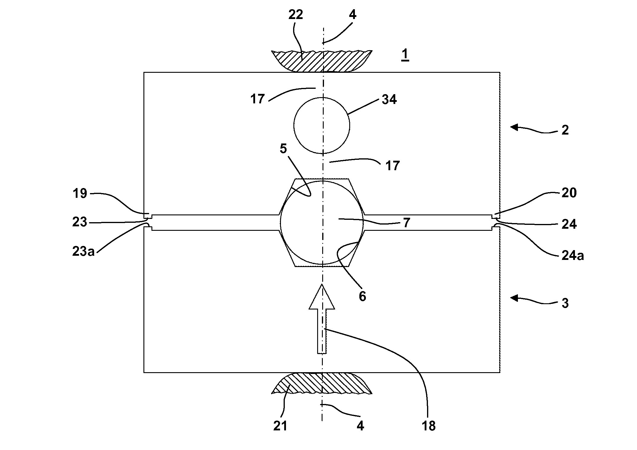
[0037]The invention relates to a crimping tool, in particular crimping pliers 1, with any drive mechanism, in particular manually activated hand levers or an electric or hydraulic drive. The crimping pliers 1 (besides the inventive features described in the following) might have any design or construction known from prior art. In particular, the crimping pliers 1 might have activation mechanisms, a force locking unit, a locator or a head of the pliers or other constructive details known from crimping pliers distributed by the present applicant, in particular known from documents U.S. Pat. No. 4,794,780, U.S. Pat. No. 5,153,984, EP 0 471 977 B1, U.S. Pat. No. 5,187,968, DE 44 27 553 C2, U.S. Pat. No. 5,913,933, DE 197 09 639 A1, DE 197 53 436 C2, U.S. Pat. No. 6,053,025, U.S. Pat. No. 6,026,671, DE 298 03 336 U1, U.S. Pat. No. 6,155,095, DE 198 34 859 C2, U.S. Pat. No. 6,286,358, U.S. Pat. No. 6,289,712, U.S. Pat. No. 6,474,130, U.S. Pat. No. 6,612,147, U.S. Pat. No. 6,877,228, DE 10...


PUM

PropertyMeasurementUnit
elastic degree of freedomaaaaaaaaaa
angle of inclinationaaaaaaaaaa
ejection forceaaaaaaaaaa

Abstract

The present invention relates to a crimping tool, in particular crimping pliers. The crimping tool comprises crimping die halves having a resilient deformation region. At the end of a crimping process the resilient deformation region is elastically deformed with the result that the crimping contour opens and contour parts automatically move apart. Accordingly, the crimping contour “breaks free” from the work piece for an ease of the removal of the work piece from the crimping tool.

Description

CROSS REFERENCE TO RELATED APPLICATIONS[0001]This application claims priority to co-pending German Patent Application No. DE 10 2009 001 949.9 entitled “Gesenkhalfte and Presswerkzeug”, filed Mar. 27, 2009.FIELD OF THE INVENTION[0002]The present invention generally relates to a crimping tool which might be driven by hand or by a hydraulic, an electrical or any other drive and which is used for crimping a work piece. Without restricting the invention to the following examples, the work piece might be a fitting for connecting tubes or conduits, a cable shoe, a sleeve for an end of a cable, a plug, a crimp connection without lead, a double connection for a wire and an insulation of the wire, a socket or a connecting element for an electrical cable or an optical fiber cable.BACKGROUND OF THE INVENTION[0003]When using crimping tools, it might happen that the work piece keeps attached or sticks to the crimping contour of the crimping die halves at the end of the crimping process. To remov...

Claims


Application Information

Patent Timeline
Patent Type & Authority Applications(United States)
IPC IPC(8): B21D11/00
CPCB21J13/02B21K25/00B30B15/065B25B27/10B21D39/048B25B27/146H01R43/058B21D45/00
Inventor BATTENFELD, KURTGLOCKSEISEN, THOMAS
Owner WEZAG - WERKZEUGFAB
Why Eureka
Try Eureka