Apparatus and method for laminating solar modules

a technology of solar modules and apparatuses, applied in the direction of lamination, electrical equipment, mechanical control devices, etc., can solve the problem of avoiding the source of inaccuracy, and achieve the effect of reducing costs, reducing material consumption and wear, and improving accuracy

Inactive Publication Date: 2010-09-30
KOMAX HOLDING
View PDF5 Cites 21 Cited by
  • Summary
  • Abstract
  • Description
  • Claims
  • Application Information

AI Technical Summary

Benefits of technology

[0011]The purpose of the present invention is to provide an apparatus, and a corresponding method that makes use of this apparatus, with which a greater accuracy can be attained, cutting is generally optimized—through, for example, in particular no cutting mats being used, less material consumption and wear occur, and thereby the costs are reduced.

Problems solved by technology

This also obviates the source of inaccuracies that occur through the transfer of the lamination foil from the form-cutting process to the laying process.

Method used


Image

  • Apparatus and method for laminating solar modules
  • Apparatus and method for laminating solar modules
  • Apparatus and method for laminating solar modules

Examples


Embodiment Construction

[0054]The following detailed description and appended drawings describe and illustrate various exemplary embodiments of the invention. The description and drawings serve to enable one skilled in the art to make and use the invention, and are not intended to limit the scope of the invention in any manner. In respect of the methods disclosed, the steps presented are exemplary in nature, and thus, the order of the steps is not necessary or critical.

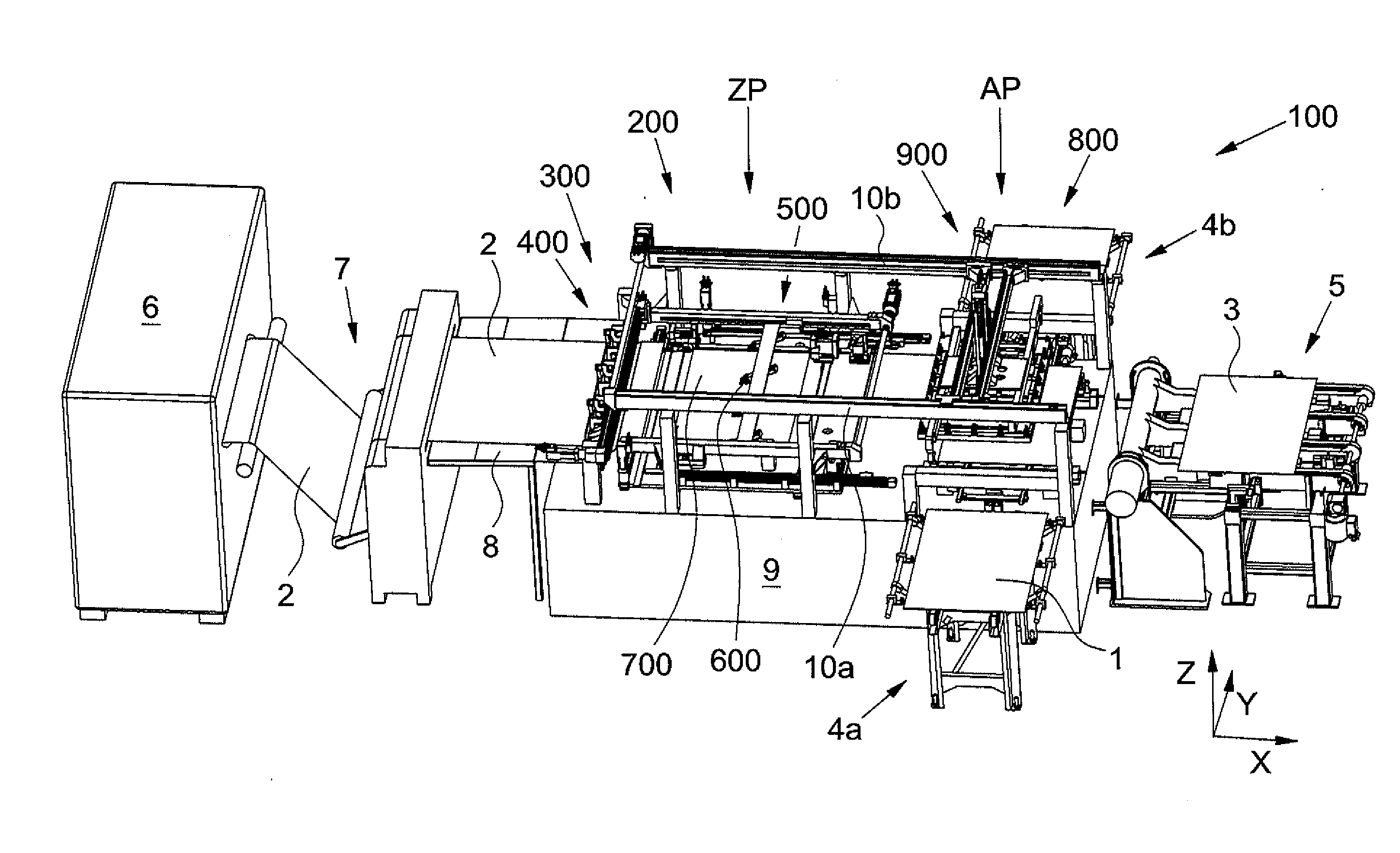
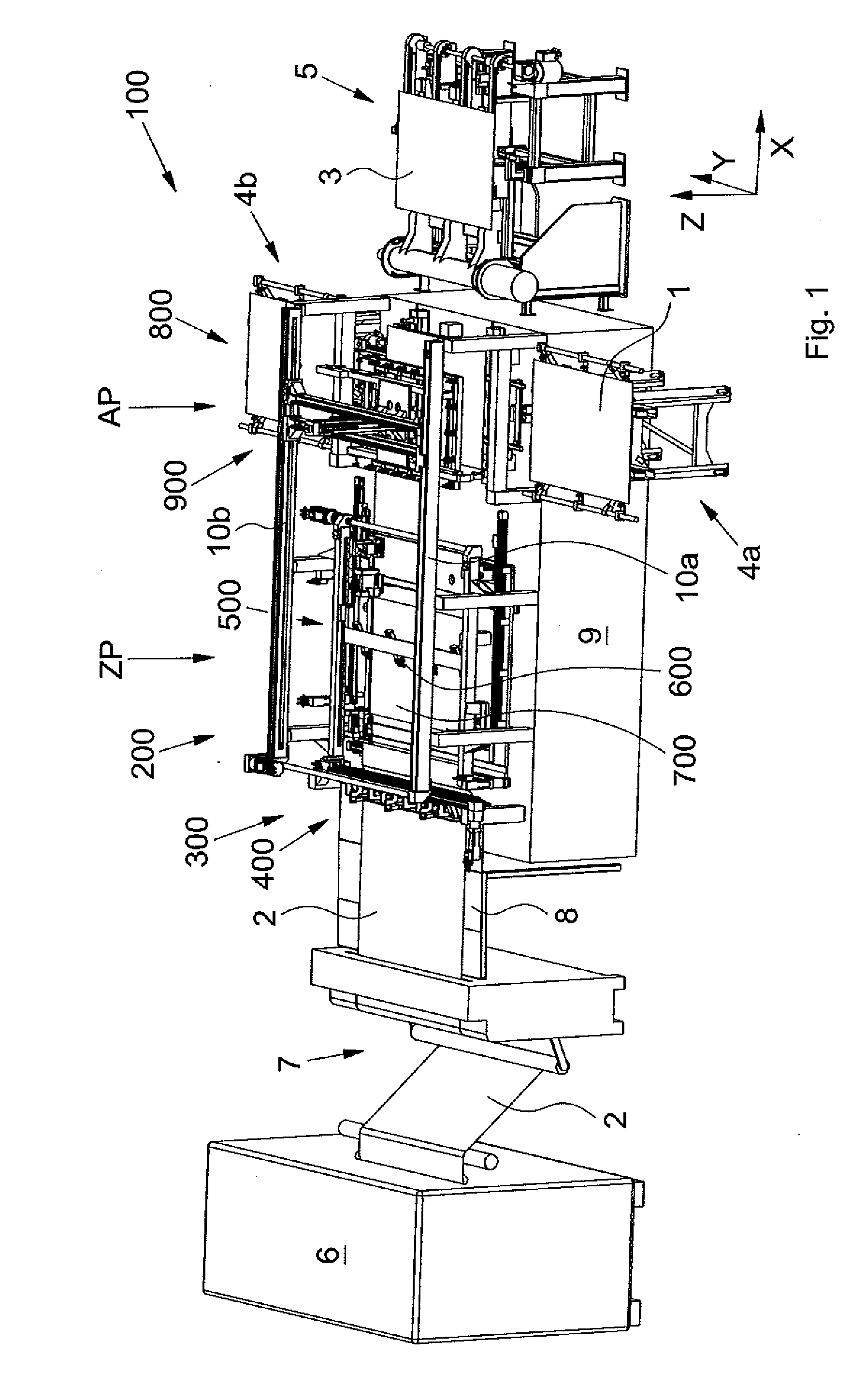
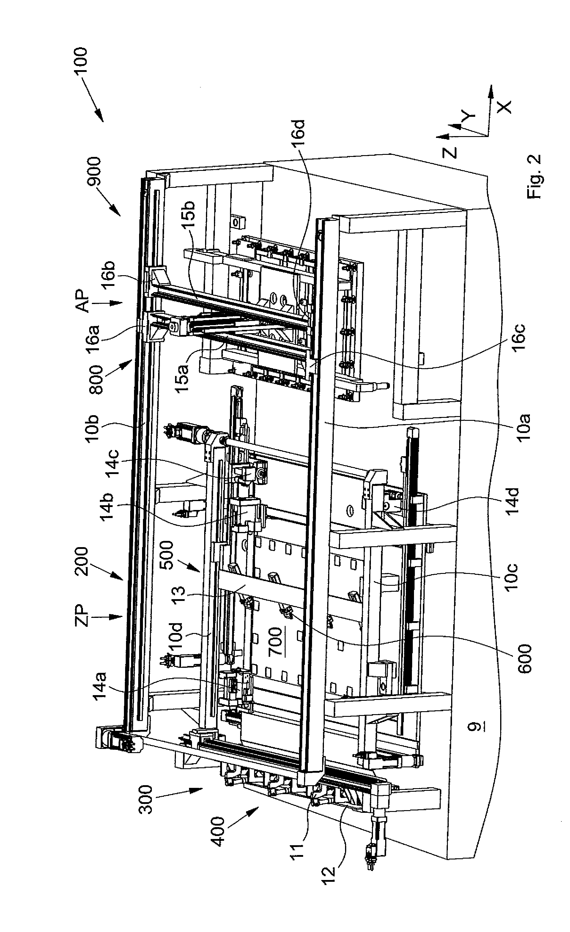
[0055]FIG. 1 shows a diagrammatic and perspective illustration of an apparatus 100 according to the invention, or of a production line 100 according to the invention, for laminating solar modules, i.e. for form-cutting and laying a lamination foil 2 onto a carrier plate 1, or onto a cover plate, which is fed by a transport system 4a of the apparatus 100. The apparatus 100 can be a closed production line, whose end-product is the laminated solar module, or be integrated in a furthergoing production line which also executes the laminating oper...


PUM

PropertyMeasurementUnit
timeaaaaaaaaaa
angleaaaaaaaaaa
angleaaaaaaaaaa

Abstract

An apparatus for laminating a solar module includes a form-cutting unit for form-cutting lamination foil, a holding apparatus for holding the laminating foil in a form-cutting position when form-cutting with at least one cutter, and a laying unit for laying a form-cut laminating foil piece in a laying position on a carrier plate. The apparatus further includes a cutting-off unit for cutting-off the piece of lamination foil from a foil unroller and a pull-out unit for pulling-out the lamination foil into the form-cutting position on a cutting table.

Description

FIELD OF THE INVENTION[0001]This invention relates to an apparatus and a corresponding method for the so-called lamination of solar modules with this apparatus. The invention relates particularly to a production line for the form-cutting and application, or laying, of lamination foils in the manufacture of solar modules.BACKGROUND OF THE INVENTION[0002]In principle, photovoltaic or solar modules are manufactured in that, on a front-side carrier plate made of, for example, glass, from its back-side, i.e. with the optically active side down, the individual solar cells and their connecting contacts (strings), or foils coated with the light-sensitive substances, are laminated with a back-side cover plate or cover foil. Immediately thereafter, or in a later work operation, the stacked layers are laminated by underpressure and heating.[0003]Accordingly, use is made of, for example, lamination foils of EVA (ethylene vinyl acetate), PVB (polyvinyl butyral) or ionomers (thermoplastic materia...

Claims


Application Information

Patent Timeline
Patent Type & Authority Applications(United States)
IPC IPC(8): B32B38/04B32B37/02
CPCB32B38/0004B32B38/18B32B38/1858B32B2457/12Y10T156/1062H01L31/1876Y02E10/50Y10T156/12H01L31/048Y02P70/50
Inventor KAUFMANN, STEFANGRATZER, WALTER
Owner KOMAX HOLDING
Why Eureka
Try Eureka