Method and a device for optimizing the operation of propulsive propellers disposed on either side of a rotorcraft fuselage

a technology of left and right propulsive propellers and fuselage, which is applied in the direction of propellers, rotorcraft, position/direction control, etc., can solve the problem of limited pilot's margin for maneuvering in yaw with the propeller closest to its limit, and the difference between the first torque generated by the left propeller and the second torque generated by the right propeller

Active Publication Date: 2010-09-30
EUROCOPTER
View PDF8 Cites 16 Cited by
  • Summary
  • Abstract
  • Description
  • Claims
  • Application Information

AI Technical Summary

Benefits of technology

[0038]An object of the present invention is thus to propose a method and a device that make it possible to optimize the operation of the left and right propellers of a rotorcraft having a main lift rotor driven by a power plant during at least one stage of flight, or indeed continuously in the context of a hybrid helicopter.

Problems solved by technology

This difference also gives rise to a difference between the first torque generated by the left propeller and the second torque generated by the right propeller that can, under extreme circumstances, become problematic.
If one propeller is close to its maximum admissible torque, then the pilot's margin for maneuvering in yaw with the propeller that is closest to its limit consequently becomes limited.
Thus, the state of the art does not provide precise teaching for optimizing the operation of left and right propellers of a rotorcraft having a main lift rotor driven by a power plant during at least one stage of flight.
Consequently, the above-mentioned documents do not make it possible to solve the problem that is posed.

Method used


Image

  • Method and a device for optimizing the operation of propulsive propellers disposed on either side of a rotorcraft fuselage
  • Method and a device for optimizing the operation of propulsive propellers disposed on either side of a rotorcraft fuselage
  • Method and a device for optimizing the operation of propulsive propellers disposed on either side of a rotorcraft fuselage

Examples


Embodiment Construction

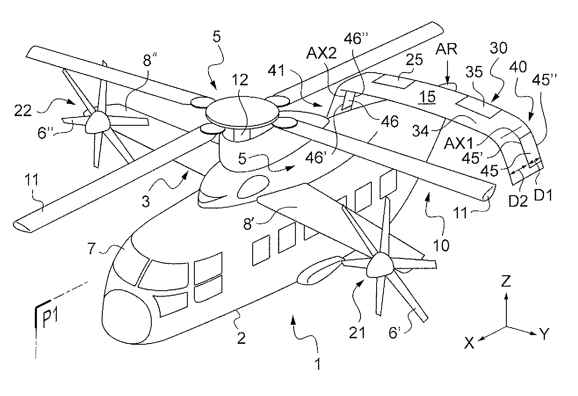
[0109]It should be observed that FIG. 1 shows three mutually orthogonal directions X, Y, and Z.

[0110]The direction X is referred to as the longitudinal direction and the direction Y as the transverse direction.

[0111]Finally, the third direction Z is referred to as the elevation direction.

[0112]FIG. 1 shows a hybrid helicopter 1 comprising a fuselage 2 with a cockpit 7 at the front, a main rotor 10 for driving blades 11 in rotation firstly by virtue of a power plant 5′ having two turbine engines 5 disposed on top of the fuselage 2 on either side of the longitudinal plane of symmetry P1 of the fuselage 2, and secondly by virtue of a first main gearbox.

[0113]It should be observed that the two turbine engines 5 are not visible in FIG. 1 because of the presence of fairings.

[0114]Furthermore, the hybrid helicopter 1 has a high wing 3 made up of two half-wings 8′ and 8″ attached to the top of the fuselage 2.

[0115]The hybrid helicopter 1 is propelled in particular by a left propeller 21 and...


PUM


Abstract

A method of optimizing the operation of left and right propellers disposed on either side of the fuselage of a rotorcraft including a main rotor. Left and right aerodynamic surfaces include respective left and right flaps suitable for being deflected, yaw stabilization of the rotorcraft being achieved via first and second pitches respectively of the left and right propellers, and the deflection angles of the left and right flaps are adjusted solely during predetermined stages of flight in order to minimize a differential pitch of the left and right propellers so as to optimize the operation of the left and right propellers, the predetermined stages of flight including stages of flight at low speed performed at an indicated air speed (IAS) of the rotorcraft that is below a predetermined threshold, and stages of yaw-stabilized flight at high speed performed at an indicated air speed of the rotorcraft greater than the predetermined threshold.

Description

FIELD OF THE INVENTION[0001]The present invention relates to a method and to a device for optimizing the operation of left and right propulsive propellers disposed on either side of a rotorcraft fuselage.[0002]Thus, the invention relates to a rotorcraft fitted with propulsive propellers disposed on either side of the fuselage of the rotorcraft, the main lift rotor of the rotorcraft being set into rotation by a power plant at least during a portion of a flight.[0003]By way of example, the rotorcraft may be a hybrid helicopter.BACKGROUND OF THE INVENTION[0004]A hybrid helicopter relates to an advanced concept for a vertical takeoff and landing (VTOL) aircraft.[0005]This advanced-concept hybrid helicopter, as described in document FR 2 916 418, associates at reasonable cost the effectiveness in vertical flight of a conventional helicopter with the high-speed travel performance made possible by using propulsive propellers and modern turbine engines.[0006]Thus, a hybrid helicopter is nei...

Claims


Application Information

Patent Timeline
Patent Type & Authority Applications(United States)
IPC IPC(8): B64C27/22B64C27/04
CPCB64C2027/8272B64C27/26
Inventor QUEIRAS, NICOLASSALESSE-LAVERGNE, MARCEGLIN, PAUL
Owner EUROCOPTER
Why Eureka
Try Eureka