Wiring structures

Active Publication Date: 2010-09-30
SAMSUNG ELECTRONICS CO LTD
View PDF21 Cites 19 Cited by
  • Summary
  • Abstract
  • Description
  • Claims
  • Application Information

AI Technical Summary

Benefits of technology

[0022]According to example embodiments, the wiring structure may have a relatively low resistance and an enhanced structural stability while ensuring a reduced parasitic

Problems solved by technology

However, this approach is limited in its ef

Method used


Image

  • Wiring structures
  • Wiring structures
  • Wiring structures

Examples


Example

[0034]The example embodiments are described more fully hereinafter with reference to the accompanying drawings. The inventive concepts may, however, be embodied in many different forms and should not be construed as limited to the example embodiments set forth herein. In the drawings, the sizes and relative sizes of layers and regions may be exaggerated for clarity.

[0035]It will be understood that when an element or layer is referred to as being “on,”“connected to” or “coupled to” another element or layer, it can be directly on, connected or coupled to the other element or layer or intervening elements or layers may be present. In contrast, when an element is referred to as being “directly on,”“directly connected to” or “directly coupled to” another element or layer, there are no intervening elements or layers present. Like or similar reference numerals refer to like or similar elements throughout. As used herein, the term “and / or” includes any and all combinations of one or more of...


PUM


Abstract

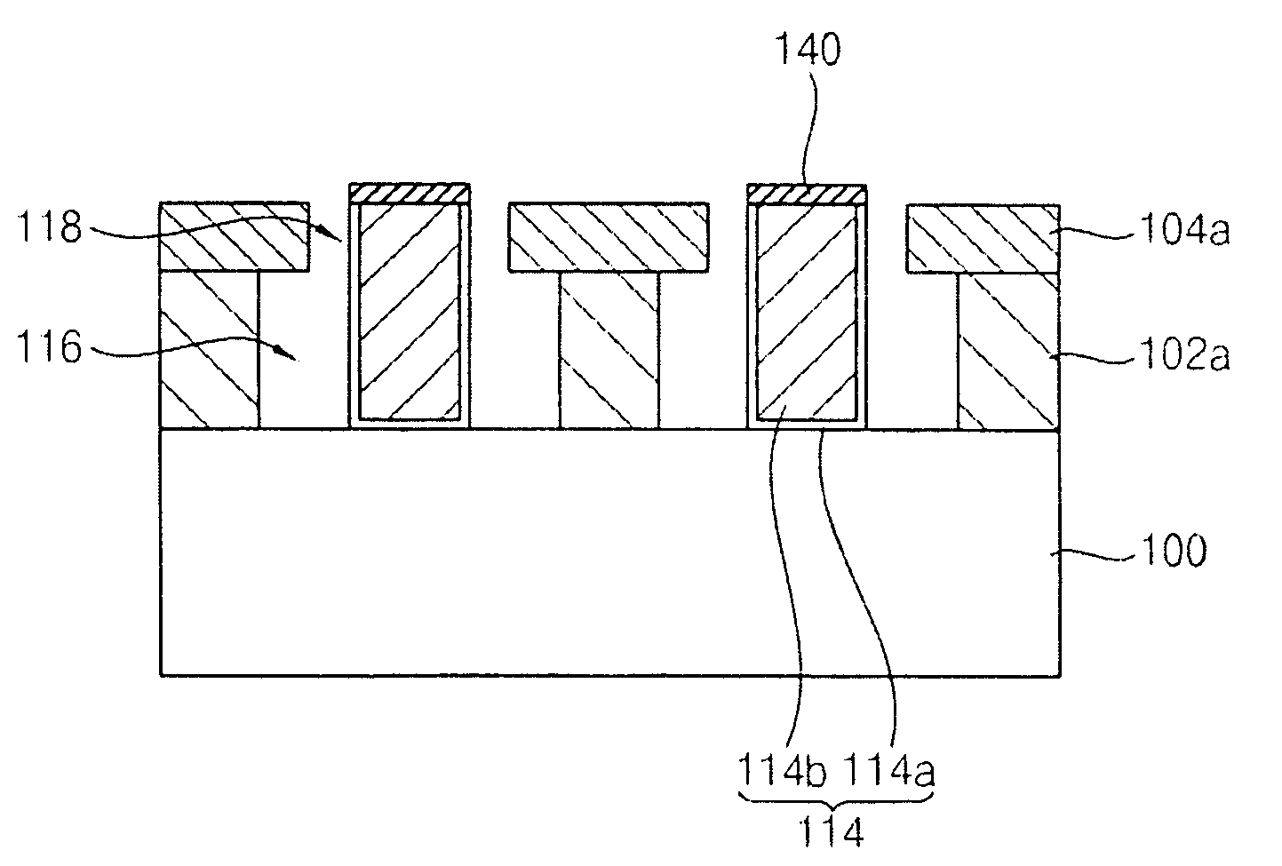
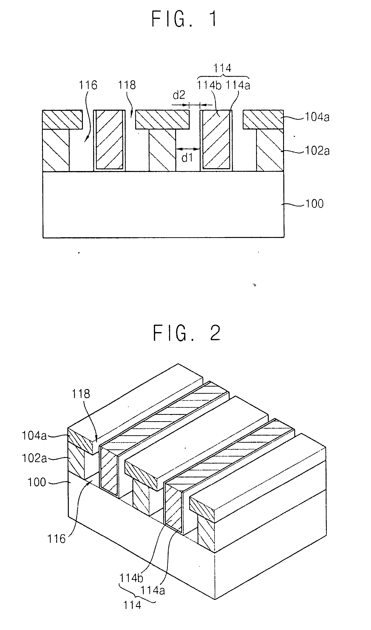
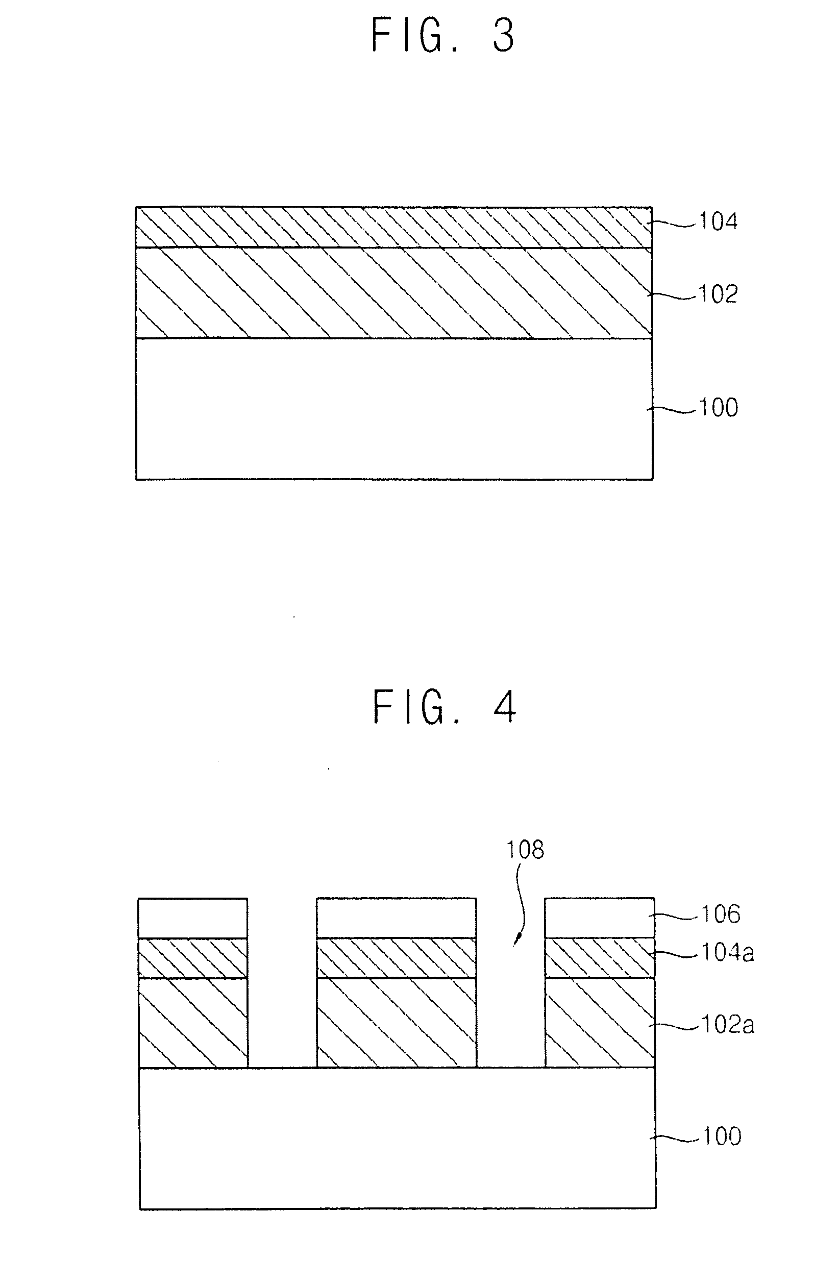
A wiring structure includes a conductive pattern on a substrate, a first insulation layer pattern between adjacent conductive patterns and a second insulation layer pattern on the first insulation layer pattern. The first insulation layer pattern is separated from the conductive pattern by a first distance to provide a first air gap. The second insulation layer pattern is spaced apart from the conductive pattern by a second distance substantially smaller than the first distance to provide a second air gap. The wiring structure may have a reduced parasitic capacitance while simplifying processes for forming the wiring structure.

Description

RELATED APPLICATIONS[0001]This application claims priority under 35 U.S.C. §119 to Korean patent Application No. 10-2009-0025748, filed on Mar. 26, 2009, the disclosure of which is hereby incorporated by reference herein in its entirety.BACKGROUND[0002]1. Technical Field[0003]Example embodiments relate to a wiring structure and a method of forming a wiring structure. More particularly, example embodiments relate to a wiring structure effective for reducing a parasitic capacitance and a method of forming the wiring structure.[0004]2. Description of the Related Art[0005]As semiconductor devices continue to become more highly integrated, the size of wirings, or interconnects, and the size of spacing between wirings in a semiconductor device continue to become more considerably decreased. It is preferred that the wirings in the semiconductor device have low resistance even though the wirings have greatly reduced widths; accordingly, the wirings are generally formed using metal having a ...

Claims


Application Information

Patent Timeline
IPC IPC(8): H01L23/532
CPCH01L21/7682H01L21/76831H01L21/76835H01L21/76849H01L23/5222H01L2924/0002H01L23/53295H01L2221/1063H01L2924/00H01L21/28
Inventor LEE, KYOUNG-WOO
Owner SAMSUNG ELECTRONICS CO LTD
Why Eureka
Try Eureka