Producing full-color image using cfa image

a filter array and image technology, applied in the field of color filter array images, can solve the problems of reducing the quality of cfa images, and reducing the blur of image capture devices, so as to improve the quality of full-resolution color images, reduce motion blur, and reduce the effect of blur

Active Publication Date: 2010-09-30
OMNIVISION TECH INC
View PDF88 Cites 28 Cited by
  • Summary
  • Abstract
  • Description
  • Claims
  • Application Information

AI Technical Summary

Benefits of technology

[0020]An advantage of the present invention is that improved full-resolution color images with reduced motion blur can be produced without having to use a photographic flash or long exposure times to properly expose a single image.
[0021]A further advantage of the present invention is that fill-resolution color images with reduced image capture device-induced blur can be produced without the need for a costly image stabilization system having moveable lens system or special imager position

Problems solved by technology

Much of the light is lost when passing through the optical path of the electronic imaging system.
Typically, about 5% of the light is lost due to lens reflections and haze and about 60% is lost because of the color filter array.
It is well known, however, that longer exposures can result in blurry images.
However, this method under-exposes the electronic image sensor during image capture so dark images are generated.
An analog or digital gain can be applied to the image signal to brighten the dark images, but those skilled in the art will recognize that this will result in noisy images.
High-grade optical elements with large apertures, which can gather more light and preserve more light passing through them, are therefore not practicable.
However, flash photography is only practical if the distance between the flash and the object is relatively small.
Additionally, a flash adds extra cost and weight to an image capture device.
A disadvantage of this approach is that the extrapolated pixel values of an object that is already in motion when the exposure begins are highly uncertain.
The image brightness, as seen by the sensor, never has a constant value and, therefore, the uncertainty in the extrapolated pixel values results in an image with motion artifacts.
Another disadvantage is that it us

Method used


Image

  • Producing full-color image using cfa image
  • Producing full-color image using cfa image
  • Producing full-color image using cfa image

Examples


Embodiment Construction

[0031]In the following description, a preferred embodiment of the present invention will be described in terms that would ordinarily be implemented as a software program. Those skilled in the art will readily recognize that the equivalent of such software can also be constructed in hardware. Because image manipulation algorithms and systems are well known, the present description will be directed in particular to algorithms and systems forming part of, or cooperating more directly with, the system and method in accordance with the present invention. Other aspects of such algorithms and systems, and hardware or software for producing and otherwise processing the image signals involved therewith, not specifically shown or described herein, can be selected from such systems, algorithms, components and elements known in the art. Given the system as described according to the invention in the following materials, software not specifically shown, suggested or described herein that is usef...


PUM


Abstract

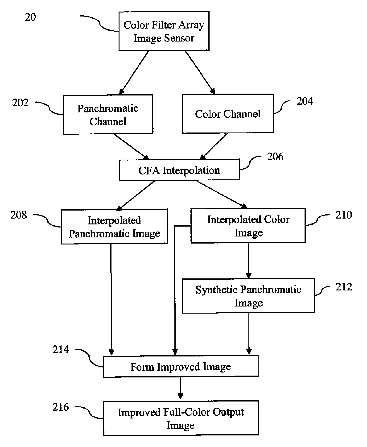
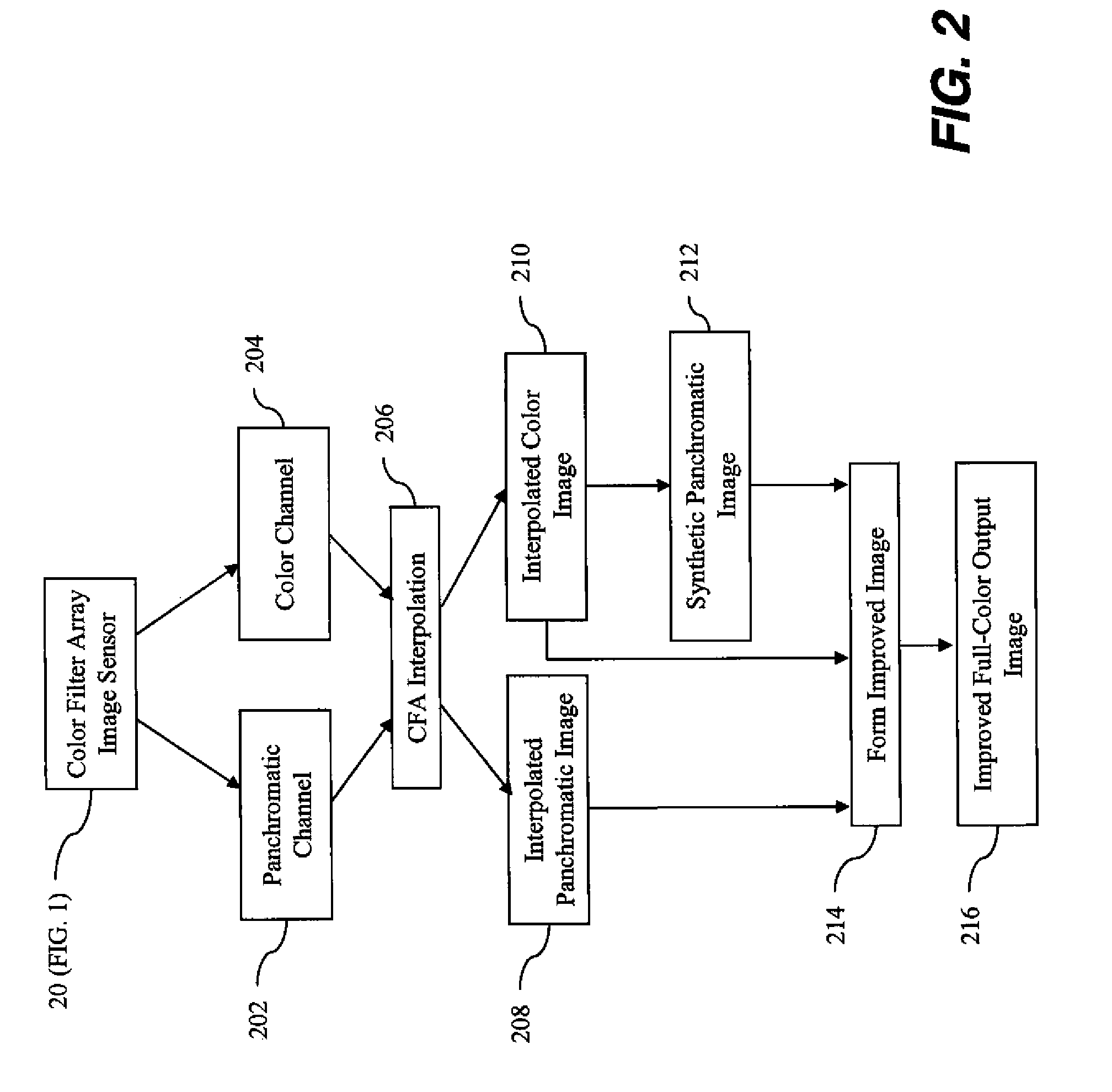
A method of forming a full-color output image using a color filter array image having a plurality of color channels and a panchromatic channel, comprising capturing a color filter array image having a plurality of color channels and a panchromatic channel, wherein the panchromatic channel is captured using a different exposure time than at least one of the color channels; computing an interpolated color image and an interpolated panchromatic image from the color filter array image; computing a chrominance image from the interpolated color image; and forming the full color output image using the interpolated panchromatic image and the chrominance image.

Description

CROSS REFERENCE TO RELATED APPLICATIONS[0001]Reference is made to commonly assigned U.S. application Ser. No. 12 / 401,002, (docket 95262) filed Mar. 10, 2009 entitled CFA IMAGE WITH SYNTHETIC PANCHROMATIC IMAGE by Kumar et al., the disclosure of which is incorporated herein by reference.FIELD OF THE INVENTION[0002]The present invention relates to color filter array images having color channels and a panchromatic channel and more particularly to providing an improved full-resolution color image with reduced motion blur.BACKGROUND OF THE INVENTION[0003]An electronic imaging system depends on a lens system to form an image on an electronic image sensor to create an electronic representation of a visual image. Examples of such electronic image sensors include charge coupled device (CCD) image sensors and active pixel sensor (APS) devices (APS devices are often referred to as CMOS sensors because of the ability to fabricate them in a Complementary Metal Oxide Semiconductor process). A sen...

Claims


Application Information

Patent Timeline
IPC IPC(8): H04N9/04G06K9/00
CPCG06T3/4015H04N9/045H04N5/23248H04N23/68H04N25/133H04N25/135
Inventor KUMAR, MRITYUNJAYADAMS, JR., JAMES E.
Owner OMNIVISION TECH INC
Why Eureka
Try Eureka