Backlight Device and Display Device
a backlight device and display device technology, applied in static indicating devices, lighting and heating apparatuses, instruments, etc., can solve the problems of large amount of heat generated, insufficient heat release measure, thick backlight units, etc., to reduce life time and luminance, suppress heat generation of light emitting diodes, and reduce the effect of chromaticity shi
- Summary
- Abstract
- Description
- Claims
- Application Information
AI Technical Summary
Benefits of technology
Problems solved by technology
Method used
Image
Examples
embodiment mode 1
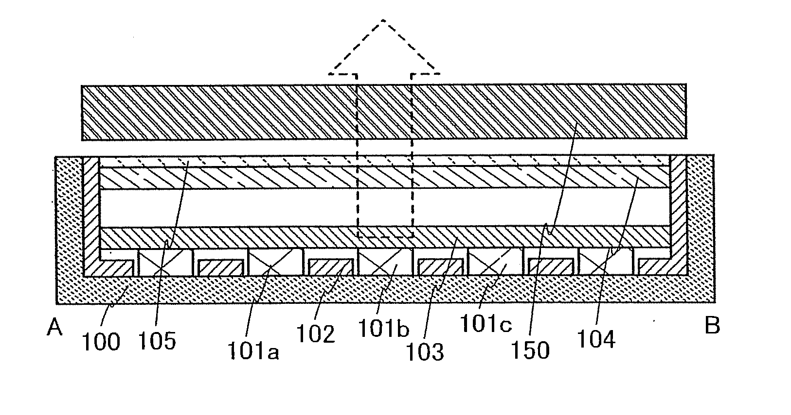
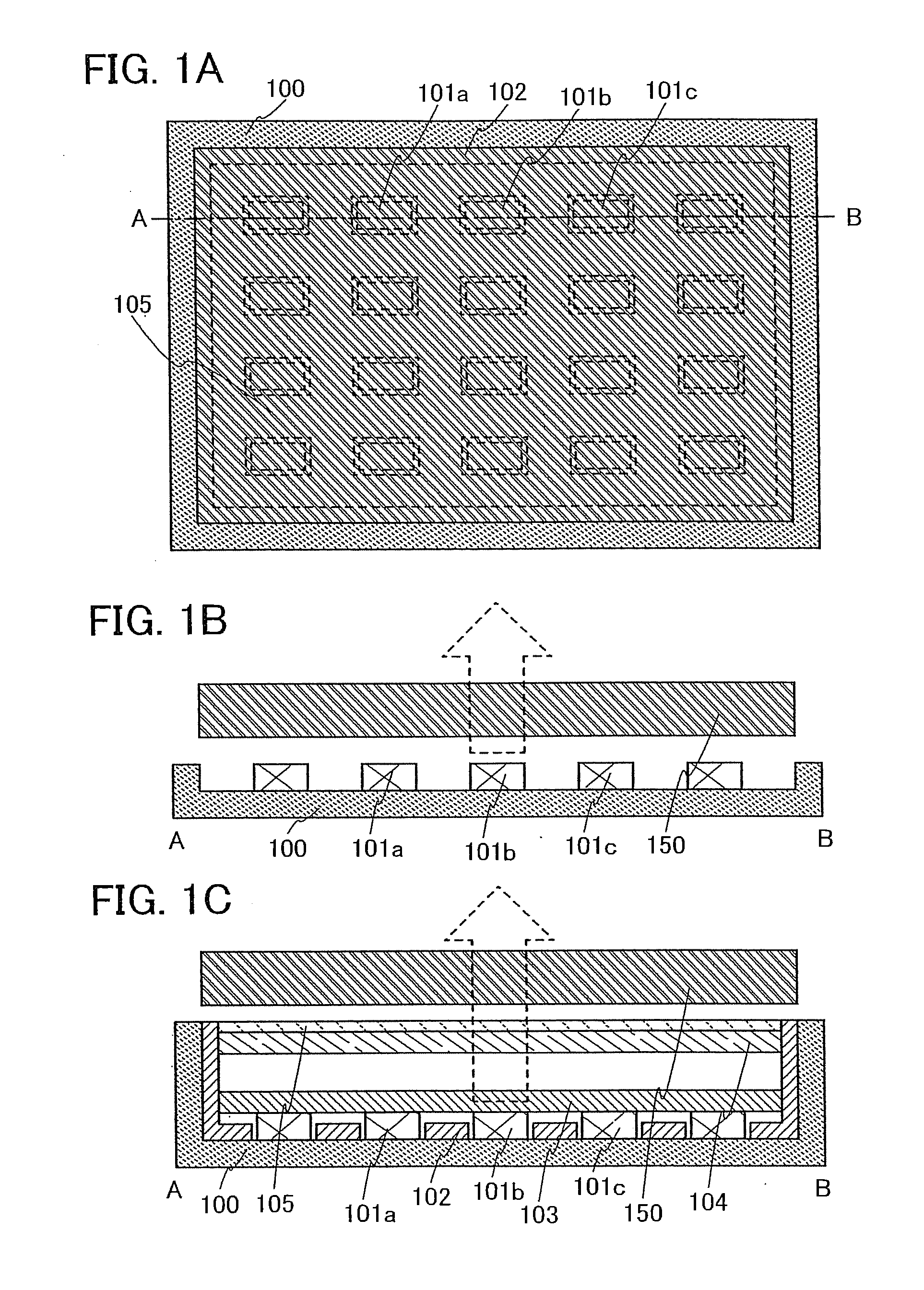
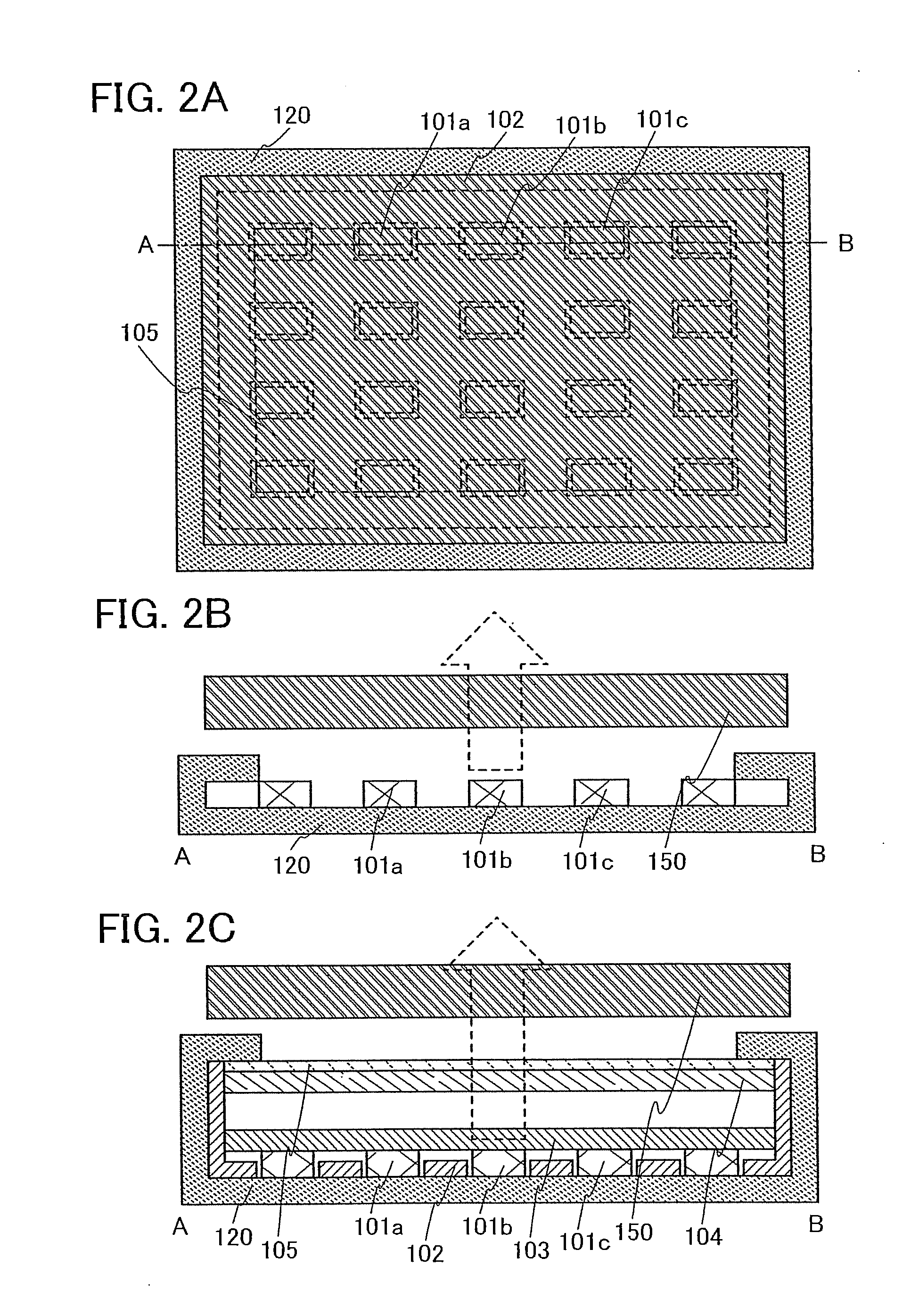
[0060]In this embodiment mode, a concept of a backlight device (also referred to as a backlight or a lighting device) and a display device provided with the backlight device of the present invention is described.
[0061]In the present invention, a light emitting diode (LED) is used as a light source of a backlight device and thermoelectric elements are provided in a chassis for holding the light emitting diode so that the thermoelectric elements surround the light emitting diode (under the light emitting diode and on the four sides thereof). A temperature in the backlight device is adjusted by cooling and heating by the thermoelectric elements. The thermoelectric element refers to an element of metal or semiconductor which converts heat energy to and from electric energy with use of a phenomenon relating heat and electricity. As an example of a thermoelectric element which can be used in the present invention, a Peltier element can be given.
[0062]FIG. 1A is a top view of a display dev...
embodiment mode 2
[0084]In this embodiment mode, a backlight device using the present invention and a display device including the backlight device are described in detail.
[0085]A display device shown in FIG. 6 includes a backlight unit 230 including a light emitting diode 201 (a light emitting element 201a, a cover 201b, and a terminal 201c), a thermal conductive layer 202 serving as a thermal conductive adhesive agent, a metal core substrate 203, a chassis 200 having a thermoelectric element, a reflective sheet 204, a light guide plate 205, a diffusing plate 206, prism sheets 207a and 207b, and a color sensor 220, and also includes a liquid crystal display panel 231 including a substrate 211, a layer 212 including a display element, a substrate 213, polarizing plates 214 and 210, and a liquid crystal display panel driving circuit 232. The backlight unit 230 further includes a temperature sensor 221 in a backlight unit region, a temperature controller 222, a thermoelectric element driving circuit 22...
embodiment mode 3
[0102]In this embodiment mode, a liquid crystal display device including a backlight device of the present invention and including a thin film transistor having a crystalline semiconductor film is described.
[0103]FIG. 16A is a top view showing a structure of a display device of the present invention, in which a pixel portion 2701 including pixels 2702 arranged in matrix, a scanning line input terminal 2703, and a signal line input terminal 2704 are formed over a substrate 2700 with an insulating surface. The number of pixels provided may be determined in accordance with various standards. For example, the number of pixels of XGA for RGB full-color display may be 1024×768×3 (RGB), the number of pixels of UXGA for RGB full-color display may be 1600×1200×3 (RGB), and the number of pixels corresponding to a full-speck high vision for RGB full-color display may be 1920×1080×3 (RGB).
[0104]The pixels 2702 are arranged in matrix provided at intersections of scanning lines extended from the ...
PUM
| Property | Measurement | Unit |
|---|---|---|
| wavelength | aaaaa | aaaaa |
| wavelength | aaaaa | aaaaa |
| wavelength | aaaaa | aaaaa |
Abstract
Description
Claims
Application Information
 - R&D
- Intellectual Property
- Life Sciences
- Materials
- Tech Scout
- Unparalleled Data Quality
- Higher Quality Content
- 60% Fewer Hallucinations
Browse by: Latest US Patents, China's latest patents, Technical Efficacy Thesaurus, Application Domain, Technology Topic, Popular Technical Reports.
© 2025 PatSnap. All rights reserved.Legal|Privacy policy|Modern Slavery Act Transparency Statement|Sitemap|About US| Contact US: help@patsnap.com


