Optical filter, projection display, and method for manufacturing optical filter

a technology of optical filter and projection display, which is applied in the field of optical filter, can solve the problems of blotting up unnecessary light completely, and the possibility of part of unnecessary light leaking from the filter, and achieve the effect of high filtering performan

Inactive Publication Date: 2010-09-30
FUJINON SANO
View PDF2 Cites 0 Cited by
  • Summary
  • Abstract
  • Description
  • Claims
  • Application Information

AI Technical Summary

Benefits of technology

[0011]It is an object of the present invention to provide an optical filter which is compact in form but can ensure a high filtering performance, and a projection type display applying such an optical filter.
[0013]The optical filter is in a flat plate-like shape and reduced in thickness, so that it can contribute to downsize optical appliances into a compact form. Besides, an unnecessary light component separated by the filtering layers is reflected toward the light-absorptive members, which are adapted to absorb the energy of the unnecessary light component to blot up same within the filter. That is to say, there is no possibility of an filtered-out unnecessary component leaking from the filter to give adverse effects on picture images.
[0015]As a shield layer, a reflective layer can be applied. By the use of a reflective shield layer, light which has permeated through an absorptive layer can be reflected back and its further travel in the direction of an adjacent filtering layer can be completely blocked. A reflective layer of this sort can be formed by deposition of a metal layer such as an Al, Cr, or Ti layer. A metal layer of this sort can totally reflect or absorb incident light (reflecting off a major part and absorbing a minor part of incident light), precluding of possibilities of light passage therethrough. Thus, a reflective shield layer can completely shut out passage of light in an assured manner. In a case where a reflective layer is employed as a shield layer, part of unnecessary light which has permeated through an absorptive layer is reflected back and cast on the absorptive layer again. That is to say, partly remaining unnecessary light is cast again on the absorptive layer and its energy is completely blotted up.
[0019]The optical filter of the present invention has a wide range of applications. For example, it can be applied to a liquid crystal projector as a polarization filter for filtering out a particular component from a light beam to be fed to a polarized beam splitter. In this case, pure and clear polarized light, free of unnecessary noisy components, can be fed to a polarized beam splitter for the purpose of improving picture quality. Besides, the optical filter can be applied to optical pickups and the like.
[0022]In the optical filter manufacturing method according to the present invention, a plural number of filter plate units, each coated with a filtering layer, are bonded together preferably by the use of an optical adhesive agent which matches with the transparent body material of the filter in refractivity and is satisfactory in transmittance, while using a heat resistant adhesive agent in the step of bonding together coated staircase blocks. Light energy absorbed by a light-absorptive layer is converted into thermal energy to put the absorptive layer in high temperature conditions. However, defoliation of an absorptive layer in high temperature conditions can be prevented by the use of a heat resistance adhesive agent.
[0023]As described above, the optical filter of the present invention is in the shape of a flat plate, achieving the objective of downsizing the filter into a compact form. In addition, by blotting up an unnecessary light component by the use of light-absorptive layers, the filter realizes a high filtering function which will lead to improvements in picture quality. Furthermore, the polarization filter manufacture method of the present invention permits to fabricate a polarization filter with high precision.

Problems solved by technology

Light-absorptive deposition film layers of this sort can be formed, for example, by alternately laminating a Cr layer and an SiO2 layer for a plural number of times. Although the light-absorptive layers function to absorb an unnecessary light component, they may fail to blot up unnecessary light completely, leaving possibilities of part of unnecessary light leaking from the filter.

Method used


Image

  • Optical filter, projection display, and method for manufacturing optical filter
  • Optical filter, projection display, and method for manufacturing optical filter
  • Optical filter, projection display, and method for manufacturing optical filter

Examples


Embodiment Construction

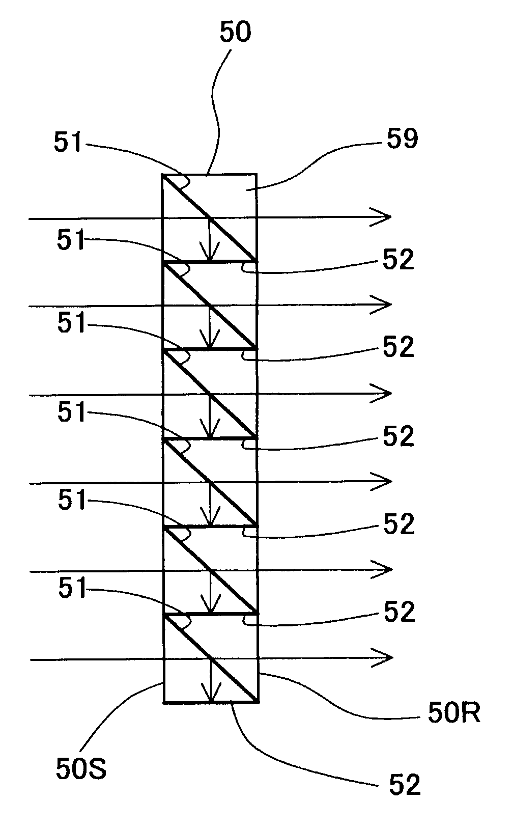
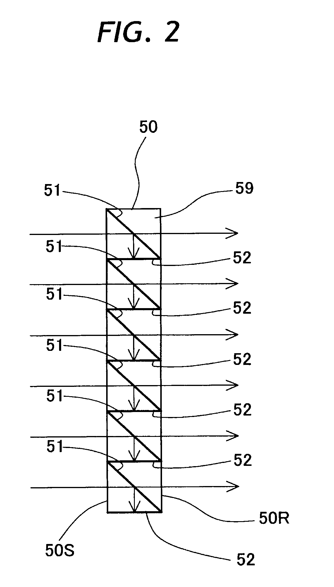
[0034]Hereafter, with reference to the accompanying drawings, the present invention is described more particularly by way of its preferred embodiments in which the optical filter is applied as a polarization filter. A polarization filter has a function of transmitting either p- or s-polarized light whichever is actually used as signal light, while filtering out or eliminating the other polarization as unnecessary light. An optical filter according to the present invention can be applied as an arbitrary optical filter intended for other purposes, for example, as an infrared filter having a function of filtering out infrared components as unnecessary light.

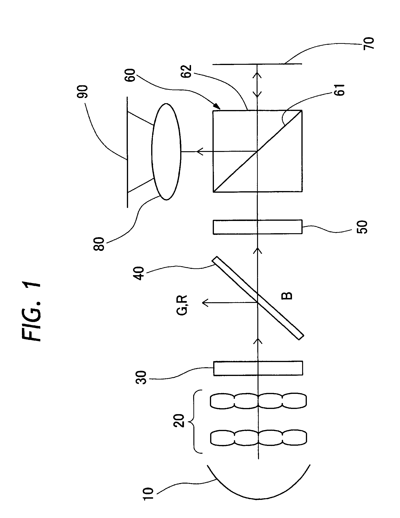
[0035]Shown schematically in FIG. 1 is part of a reflection type liquid crystal projector as an example of a projection display. The reflection type liquid crystal projector shown in FIG. 1 is composed of a light source 10, fly-eye lenses 20, a polarization converting element 30, a dichroic mirror 40, a polarization filter 50, a pol...


PUM


Abstract

An optical filter capable of removing an unnecessary component of incident light. The optical filter has a transparent body of a flat plate-like shape. A plurality of filtering layers, each that separate an unnecessary polarization component of incident light from a necessary polarization component, are formed within the transparent body in series and at uniform intervals with an angle inclination relative to the travel direction of incident light. A plurality of light-absorptive layers are formed within the transparent body in series and at uniform intervals between the filtering layers to absorb an unnecessary component reflected by the filtering layers.

Description

CROSS-REFERENCE TO RELATED APPLICATION[0001]The present application is a Continuation of U.S. Ser. No. 11 / 868,073, filed Oct. 5, 2007, which is hereby incorporated herein by reference in its entirety and claims the benefit from Japanese Patent Application Nos. 2006-277425, filed Oct. 11, 2006, and 2007-109178, filed Apr. 18, 2007.BACKGROUND OF THE INVENTION[0002]1. Field of the Art[0003]This invention relates to an optical filter adapted to transmit a specific light component alone, a projection display applying such an optical filter, and a method for manufacturing the same.[0004]2. Prior Art[0005]In a liquid crystal projector, typical of projection displays, while light from a light source is decomposed into three color components of blue, green and red by color separation using optical elements like dichroic mirrors which are capable of transmitting and reflecting specific wave ranges. The respective color components are modulated separately by the use of liquid crystal display d...

Claims


Application Information

Patent Timeline
Patent Type & Authority Applications(United States)
IPC IPC(8): G02B5/30G02B5/22G03B21/14
CPCB29D11/00634G02B5/003G03B21/14G02B27/286G02B27/285G03B21/206
Inventor KAWAMURA, YOSHIJI
Owner FUJINON SANO
Why Eureka
Try Eureka