Motor-driven supercharger

Active Publication Date: 2010-09-30
IHI CORP
80 Cites 43 Cited by

AI-Extracted Technical Summary

Problems solved by technology

Further, since the compressor impeller is close to the stator of the electric motor, there...

Method used

[0079]In the stator assembly 29 having the structure mentioned above, since the holding body 32 is formed in accordance with the mold forming, a close contact performance between the motor stator 24 and the outer sleeve 26 is extremely high. Accordingly, since it is possible to make a thermal resistance in a boundary portion between the motor stator 24 and the outer sleeve 26 extremely small, it is possible to efficiently cool the motor stator 24 by the cooling water flowing through the water cooling jacket 26b.
[0080]In accordance with the structure of the present invention mentioned above, since the outer sleeve 26 and the motor stator 24 construct the stator assembly 29 as the integral part, and the outer sleeve 26 of the stator assembly 29 and the seal plate 28 are fastened together in the axial direction between the bearing housing 16 and the compressor housing 20, it is possible to simultaneously fix the motor stator 24 to the bearing housing 16 by fixing the compressor housing 20 to the bearing housing 16. Accordingly, since the additional casing and the exclusive fixing part (the fastening device such as the bolt or the like) are not necessary for fixing the motor stator 24 to the bearing housing 16, and it is possible to reduce the number of the parts at a time of assembling, it is easy to assemble and disassemble.
[0082]Further, si...

Benefits of technology

[0039]In accordance with the structure on the basis of the present invention mentioned above, since the outer sleeve and the motor stator construct the stator assembly as the integral part, and the outer sleeve of the stator assembly and seal plate are fastened together in the axial direction between the bearing housing ad the compressor housing, it is possible to simultaneously fix the motor stator to the bearing housing by fixing the compressor housing to the bearing housing. Accordingly, since the additional casing for fixing the motor stator 24 to the bearing housing 16 and the exclusive fixing part (the fastening device such as the bolt or the like) at a time of assembling are not necessary, and it is possible to reduce the number of the parts at a time of assembling, it is easy to assemble and disassemble.
[0040]Further, since the outer sleeve is closely attached to the outer peripheral surface of the motor stator and supports the motor stator so as to constrain the ro...

Abstract

A motor-driven supercharger is provided with a stator assembly (29) inserted and attached to a bearing housing (16), and a seal plate (28) closely attached to a compressor side of the stator assembly (29) and comparting between a compressor housing (20) and a motor stator (24). The stator assembly (29) has the motor stator (24) and an outer sleeve (26) having an inner peripheral surface closely attached to an outer peripheral surface of the motor stator (24) and supporting the motor stator (24) in such a manner as to constrain a rotation of the motor stator (24), the motor stator (24) and the outer sleeve (26) form an integral part so as to construct the stator assembly (29), and the outer sleeve (26) constructs a liquid tight water cooling jacket between the outer sleeve and the bearing housing. The outer sleeve (26) and the seal plate (28) are fastened together in an axial direction between the bearing housing (16) and the compressor housing (20).

Application Domain

Technology Topic

Image

  • Motor-driven supercharger
  • Motor-driven supercharger
  • Motor-driven supercharger

Examples

  • Experimental program(1)

Example

[0052]A description will be in detail given below of preferable embodiments in accordance with the present invention with reference to the accompanying drawings. In this case, in each of the drawings, the same reference numerals are attached to the common portions, and an overlapping description will be omitted.
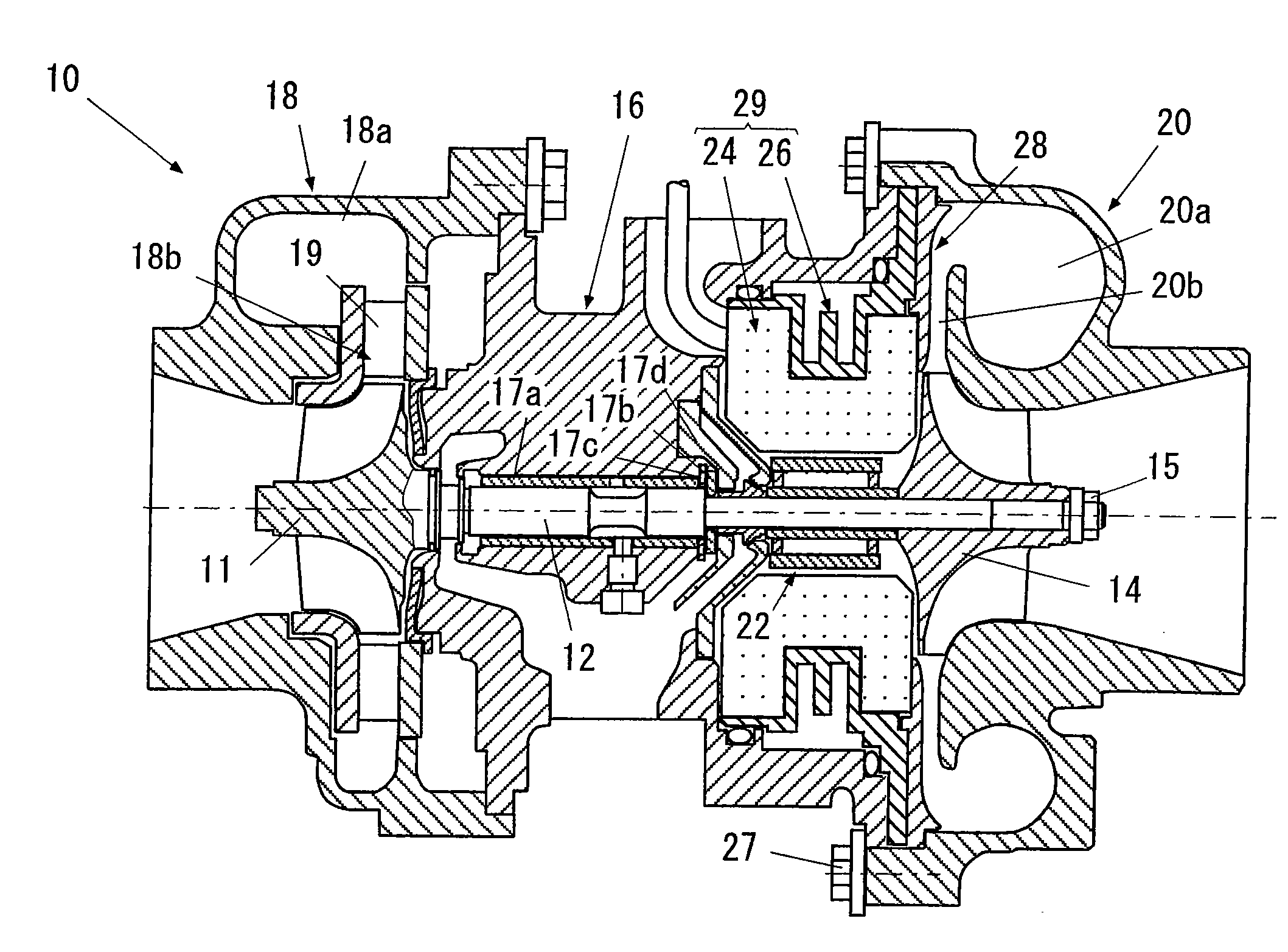
[0053]FIG. 4 is a schematic view of a whole of a motor-driven supercharger in accordance with a first embodiment of the present invention. In this drawing, a motor-driven supercharger 10 in accordance with the present invention is provided with a turbine shaft 12, a compressor impeller 14, and a housing. The housing is constituted by a bearing housing 16, a turbine housing 18 and a compressor housing 20 in this embodiment.
[0054]The turbine shaft 12 has a turbine impeller 11 in one end (a left end in the drawing). In this embodiment, the turbine impeller 11 is integrally formed in the turbine shaft 12, however, the present invention is not limited to this, but may be structured such that the turbine impeller 11 is independently attached.
[0055]The compressor impeller 14 is coupled to the other end (a right end in the drawing) of the turbine shaft 12 by an end nut 15 so as to be integrally rotated.
[0056]The bearing housing 16 rotatably supports the turbine shaft 12 by a bearing metal 17a. Further, the turbine shaft 12 is supported by a thrust collar 17b and thrust bearings 17c and 17d so as to be prevented from moving in an axial direction. Further, the bearing housing 16 has a lubricating oil flow path (not shown) for lubricating the bearing metal 17a, the thrust collar 17b and the thrust bearings 17c and 17d.
[0057]The turbine housing 18 rotatably surrounds the turbine impeller 11, and is coupled to the bearing housing 16. The turbine housing 18 has, in an inner portion, a scroll chamber 18a in which an exhaust gas is introduced from an outer portion, and an annularly formed flow path 18b guiding an exhaust gas from the scroll chamber 18a to the turbine impeller 11.
[0058]Further, a plurality of nozzle vanes 19 are arranged in the flow path 18b at a fixed interval in a peripheral direction. The nozzle vane 19 is constituted by a variable nozzle vane, and it is preferable that the nozzle vane 19 can change a flow path area formed therebetween. However, the present invention is not limited to this, but the nozzle vane may be constituted by a fixed nozzle vane.
[0059]Further, it is possible to employ an embodiment in which the nozzle vane 19 is not provided in the flow path 18b.
[0060]The compressor housing 20 rotatably surrounds the compressor impeller 14 and is coupled to the bearing housing 16. The compressor housing 20 has a scroll chamber 20a in which a compressed air is introduced to an inner portion, and an annularly formed flow path 20b guiding a compressed air to the scroll chamber 20a from the compressor impeller 14.
[0061]In accordance with the structure mentioned above, it is possible to rotationally drive the turbine impeller 11 by the exhaust gas of the engine, it is possible to transmit the rotating force to the compressor impeller 14 via the turbine shaft 12, and it is possible to compress the air by the compressor impeller 14 so as to supercharge to the engine.
[0062]In FIG. 4, the motor-driven supercharger 10 in accordance with the present invention is further provided with a motor rotor 22, a stator assembly 29 and a seal plate 28.
[0063]The motor rotor 22 is constituted by a rotor of the electric motor. A hollow portion is provided in the motor rotor 22, the turbine shaft 12 is inserted to the hollow portion, and the motor rotor 22 and the turbine shaft 12 are integrally rotated.
[0064]The stator assembly 29 corresponds to a part which is inserted and attached to the bearing housing 16, and has a motor stator 24 and an outer sleeve 26 having an inner peripheral surface closely attached to an outer peripheral surface of the motor stator 24 and supporting the motor stator 24 so as to constrain a rotation of the motor stator 24. The motor stator 24 and the outer sleeve 26 form an integral part so as to construct a stator assembly 29.
[0065]The motor stator 24 corresponds to a stator of the electric motor. A brushless a.c. motor is structured by the motor rotor 22 and the motor stator 24. It is preferable that the a.c. motor can correspond to a high speed rotation (for example, at least 100 thousand to 200 thousand rpm) of the turbine shaft 12, and can a rotational driving at a time of accelerating and a regenerative operation at a time of decelerating. Further, it is preferable that a driving voltage of the a.c. motor is equal to or higher than a d.c. voltage (for example, 12 V) of a battery mounted on a vehicle.
[0066]The seal plate 28 corresponds to a disc-like member having an opening portion in the center, is closely attached to the compressor side of the stator assembly 29, and comparts between the compressor housing 20 and the motor stator 24. The flow path 20b mentioned above is formed between a wall portion in a front surface side of the seal plate 28, and a wall portion of the compressor housing 20 opposing to the wall portion of the seal plate 28.
[0067]FIG. 5 is a partly enlarged view of FIG. 4. As shown in FIGS. 4 and 5, the motor rotor 22 is fixed to the turbine shaft 12 or a side surface of the compressor impeller 14 in accordance with a mating.
[0068]The outer sleeve 26 has a flange portion 26a extending to an outer side in a radial direction, in an end portion in the compressor side.
[0069]Further, the motor-driven supercharger 10 in accordance with the present invention has seal members 25a and 25b sealing in a liquid tight manner between the bearing housing 16 and the outer sleeve 26 and arranged so as to be spaced in an axial direction. The seal member 25a is constituted by an O-ring sealing an outer peripheral surface of the bearing housing 16 in this embodiment, and the seal member 25b is constituted by an O-ring sealing an inner surface in an axial direction of the flange portion 26a in this embodiment. In this case, both of the seal members 25a and 25b may be constituted by an O-ring for an outer periphery or a surface, or may employ the other seals.
[0070]In accordance with this structure, a liquid tight water cooling jacket 26b is constructed between the bearing housing 16 and the outer sleeve 26. A cooling water for cooling the motor stator 24 is supplied to the water cooling jacket 26b from a cooling water supply port (not shown), and the cooling water is discharged from a cooling water discharge port (not shown).
[0071]The outer sleeve 26 and the seal plate 28 are fastened together in the axial direction between the bearing housing 16 and the compressor housing 20. In the present embodiment, the outer sleeve 26 and the seal plate 28 are sandwiched between an end surface in the compressor side of the bearing housing 16 and a step 20c formed in the compressor housing 20, and the bearing housing 16, the outer sleeve 26, the seal plate 28 and the compressor housing 20 are integrally and firmly fixed by coupling and fixing the bearing housing 16 and the compressor housing 20 by a bolt 27.
[0072]As mentioned above, the stator assembly 29 corresponds to a part in which the outer sleeve 26 and the motor stator 24 are integrated, and can be handled as a single part even before being attached to the bearing housing 16. In the present embodiment, even before being attached to the bearing housing 16, the outer sleeve 26 and the motor stator 24 are closely attached firmly, and a movement in the axial direction and a rotation of the motor stator 24 is constrained with respect to the outer sleeve 26. Accordingly, at the same time when the outer sleeve 26 is fastened together with the seal plate 28 in the axial direction between the bearing housing 16 and the compressor housing 20, the movement in the axial direction and the rotation of the motor stator 24 is constrained with respect to the bearing housing 16.
[0073]In this case, if the movement in the axial direction and the rotation of the motor stator 24 are constrained in the state of being fastened together in the axial direction between the bearing housing 16 and the compressor housing 20, some play may exist between the outer sleeve 26 and the motor stator 24, before being attached to the bearing housing 16.
[0074]Next, a description will be given in more detail of a structure of the stator assembly 29 in accordance with the present embodiment. FIG. 6 shows a cross sectional view of the stator assembly 29.
[0075]It is preferable that the outer sleeve 26 is constituted by a metal (for example, an aluminum or the like) having a good heat transfer rate. In the case that the outer sleeve 26 is constituted by the metal mentioned above, it is possible to form the outer sleeve in accordance with a cutting work or a casting. An annular concave portion 26c depressed to an inner side in a radial direction is formed in an intermediate portion in an axial direction of the outer sleeve 26.
[0076]The motor stator 24 is constituted by a hollow cylindrical iron core 30, a lead wire 31 wound around the iron core 30, and a holding body 32 covering the lead wire 31 and closely attached to the outer sleeve 26. A plurality of fins are provided in an inner peripheral portion of the iron core 30 so as to be spaced in a peripheral direction in such a manner as to protrude to an inner side and extend in an axial direction. The lead wire 31 is wound around the fin 30a. The holding body 32 is made of a synthetic resin.
[0077]The stator assembly 29 having the structure mentioned above can be manufactured in accordance with the following method.
[0078]The iron core 30 is shrink fitted to an inner peripheral portion of a portion in which the annular concave portion 26c is formed in the outer sleeve 26. Next, the lead wire 31 is wound around the fin 30a of the iron core 30. Next, both end portions of the lead wire 31 protruding from the iron core 30 are bent to an outer side in a radial direction so as to be formed in a U-shaped cross section, for example, by using a press apparatus or the like. Next, a molten mold resin is poured in a mold metal mold so as to be solidified, and the holding body 32 having the U-shaped cross section as shown in FIG. 6 is formed.
[0079]In the stator assembly 29 having the structure mentioned above, since the holding body 32 is formed in accordance with the mold forming, a close contact performance between the motor stator 24 and the outer sleeve 26 is extremely high. Accordingly, since it is possible to make a thermal resistance in a boundary portion between the motor stator 24 and the outer sleeve 26 extremely small, it is possible to efficiently cool the motor stator 24 by the cooling water flowing through the water cooling jacket 26b.
[0080]In accordance with the structure of the present invention mentioned above, since the outer sleeve 26 and the motor stator 24 construct the stator assembly 29 as the integral part, and the outer sleeve 26 of the stator assembly 29 and the seal plate 28 are fastened together in the axial direction between the bearing housing 16 and the compressor housing 20, it is possible to simultaneously fix the motor stator 24 to the bearing housing 16 by fixing the compressor housing 20 to the bearing housing 16. Accordingly, since the additional casing and the exclusive fixing part (the fastening device such as the bolt or the like) are not necessary for fixing the motor stator 24 to the bearing housing 16, and it is possible to reduce the number of the parts at a time of assembling, it is easy to assemble and disassemble.
[0081]Further, since the outer sleeve 26 is closely attached to the outer peripheral surface of the motor stator 24 and supports the motor stator 24 so as to constrain the rotation of the motor stator 24, it is possible to firmly fix the stator (the motor stator 24) of the electric motor to the bearing housing 16.
[0082]Further, since the stator assembly 29 constructs the liquid tight water cooling jacket 26b between the stator assembly 29 and the bearing housing 16, the outer wall portion (the outer sleeve 26) of the stator assembly 29 is directly cooled, whereby it is possible to efficiently cool the motor stator 24 closely attached to the outer sleeve 26.
[0083]Further, since the seal plate 28 comparts between the compressor housing 20 and the motor stator 24, and is closely attached to the compressor side of the outer sleeve 26, it is possible to set the contact area therebetween sufficiently wide, and it is possible to efficiently cool the seal plate 28 heated by the compressed air on the basis of the heat transfer from the seal plate 28 to the water cooling jacket 26b.
[0084]FIG. 7 is a view showing a feature portion of a motor-driven supercharger in accordance with a second embodiment of the present invention. In the following description of the present embodiment, portions to which particular reference is not made are the same as the structures in accordance with the first embodiment.
[0085]The outer sleeve 26 in accordance with the present embodiment is structured by integrally forming the outer sleeve 26 and the seal plate 28 in accordance with the first embodiment.
[0086]Accordingly, the outer sleeve 26 is fastened together in the axial direction between the bearing housing 16 and the compressor housing 20. Further, in the outer sleeve 26, the wall surface in the compressor side forms a passage (the flow path 20b) of the compressor discharge air.
[0087]In accordance with the present embodiment, since it is possible to reduce the number of the parts at a degree at which the seal plate 28 is omitted, it is possible to further easily assemble and disassemble. In addition, it is possible to obtain the same effects as those of the first embodiment.
[0088]FIG. 8 is a view showing a feature portion of a motor-driven supercharger in accordance with a third embodiment of the present invention. In the following description of the present embodiment, portions to which particular reference is not made are the same as the structures in accordance with the first embodiment.
[0089]The outer sleeve 26 in accordance with the present embodiment is structured by integrally forming the outer sleeve 26 and the seal plate 28 (only a portion corresponding to the outer sleeve 26) in accordance with the first embodiment, and integrally forming the motor stator 24 and the seal plate 28 (only a portion corresponding to the motor stator 24).
[0090]Accordingly, the outer sleeve 26 is fastened together in the axial direction between the bearing housing 16 and the compressor housing 20. Further, the wall surface in the compressor side of the outer sleeve 26 and the wall surface in the compressor side of the motor stator 24 form a passage (the flow path 20b) of the compressor discharge air.
[0091]In accordance with the present embodiment, since it is possible to reduce the number of the parts at a degree at which the seal plate 28 is omitted, it is possible to further easily assemble and disassemble. In addition, it is possible to obtain the same effects as those of the first embodiment.
[0092]In this case, it goes without saying that the present invention is not limited to the embodiments mentioned above, but can be variously modified within a range which does not deviate from the scope of the present invention.

PUM

no PUM

Description & Claims & Application Information

We can also present the details of the Description, Claims and Application information to help users get a comprehensive understanding of the technical details of the patent, such as background art, summary of invention, brief description of drawings, description of embodiments, and other original content. On the other hand, users can also determine the specific scope of protection of the technology through the list of claims; as well as understand the changes in the life cycle of the technology with the presentation of the patent timeline. Login to view more.

Similar technology patents

Amorphous alloy round pipe extrusion forming device and technology

ActiveCN104148430AEasy to assemble and disassembleAvoid crystallization and oxidationExtrusion diesExtrusion control devicesScrapBlock structure
Owner:滕州市产品质量监督检验所

Multi-section herb grinder

InactiveUS20180126386A1Easy to assemble and disassembleCoffee millsSpice millsHerbMaterials science
Owner:URB GRINDER CO LLC

Classification and recommendation of technical efficacy words

  • Easy to assemble and disassemble
  • Reduce number of part

Ink sheet cartridge

InactiveUS20060239743A1Easy to assemble and disassembleNumber of component increaseInk ribbon cartridgesRecording apparatusBobbin
Owner:FUNAI ELECTRIC CO LTD

Suppressor for attachment to firearm barrel

InactiveUS20120152649A1Easy to assemble and disassembleImprove structural integrityMuzzle attachmentSuppressorEngineering
Owner:LARUE MARK C

Integrated stackable battery

ActiveUS20120040221A1Easy to assemble and disassembleMitigating exposure to high voltagePrimary cell to battery groupingPrimary cell maintainance/servicingEngineeringElectrical and Electronics engineering
Owner:GM GLOBAL TECH OPERATIONS LLC

Linear compressor

InactiveUS20060091735A1Simplify structureReduce number of partReciprocating/oscillating/vibrating magnetic circuit partsWorking fluid for enginesLinear compressorOuter core
Owner:LG ELECTRONICS INC
Why Eureka
Try Eureka