Apparatus and method for cooling a superconducting magnetic assembly

a superconducting magnet and apparatus technology, applied in the direction of superconductive devices, magnetic field measurement using superconductive devices, container discharge methods, etc., can solve the problems of high cost of superconducting magnet cryogen bath, inability to meet the requirements of use, so as to simplify the overall design, installation, operation and maintenance of the system. , the effect of reducing the amount of cryogen needed

Active Publication Date: 2010-09-30
GENERAL ELECTRIC CO
View PDF4 Cites 51 Cited by
  • Summary
  • Abstract
  • Description
  • Claims
  • Application Information

AI Technical Summary

Benefits of technology

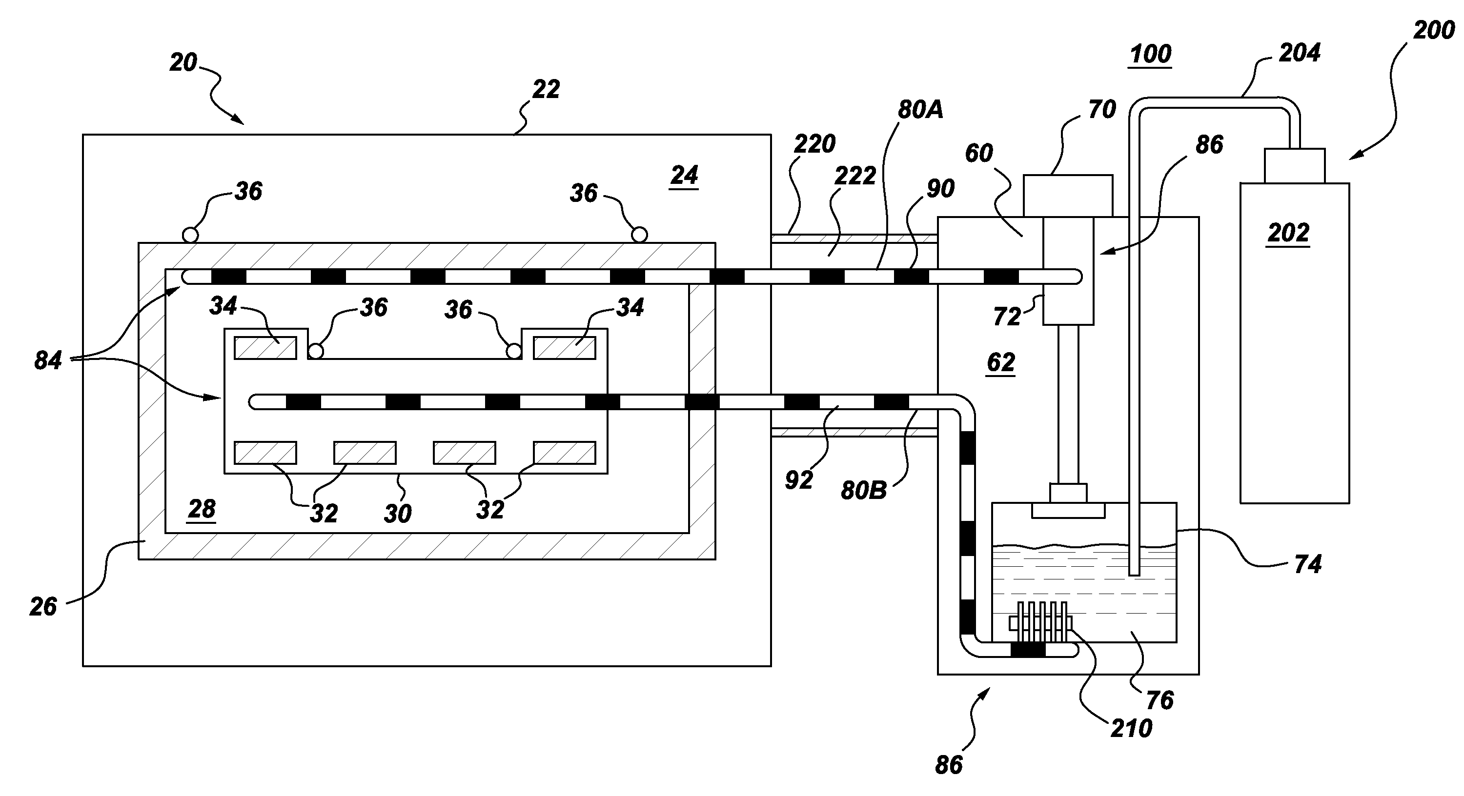
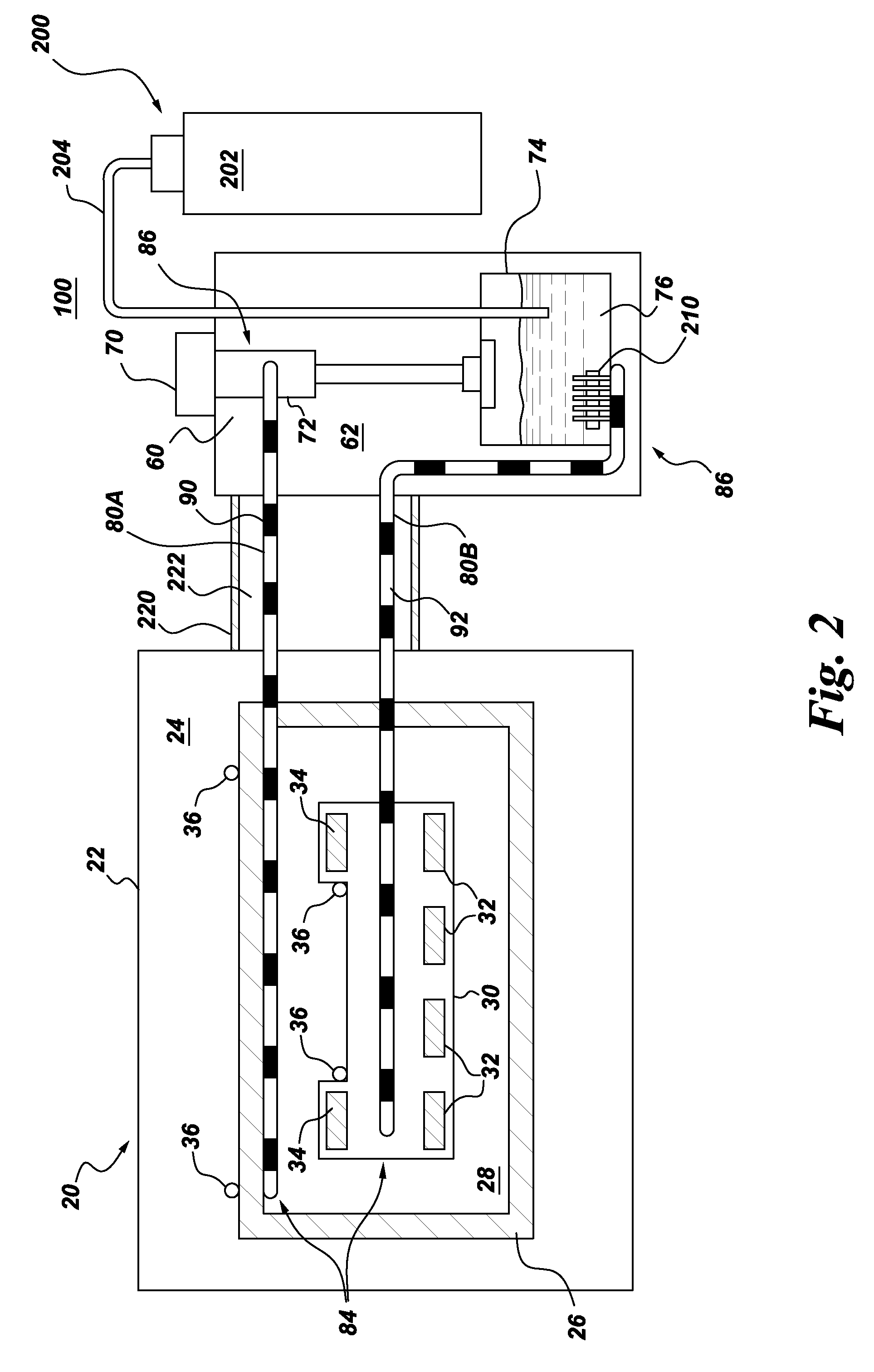
[0010]The present invention overcomes at least some of the aforementioned drawbacks by providing a superconducting magnet assembly, and a method of manufacturing a superconducting magnet assembly, that includes the reduction of the amount of cryogen needed for cooling the superconducting magnet. More specifically, an embodiment of the present invention is directed to providing a superconducting magnet assembly that employs two-phase heat transfer devices (e.g., pulsating heat tubes) for cooling which allow the location of the cryocooler to be divorced from the configuration and location of the superconducting magnet assembly, thereby simplifying the overall design, installation, operation and maintenance of the system.

Problems solved by technology

A significant cost for any system that employs superconducting magnets is for the provision of the cryogen bath.
Helium is expensive per unit volume, is not always readily obtainable, and its cost is increasing.
This has proven to be costly.
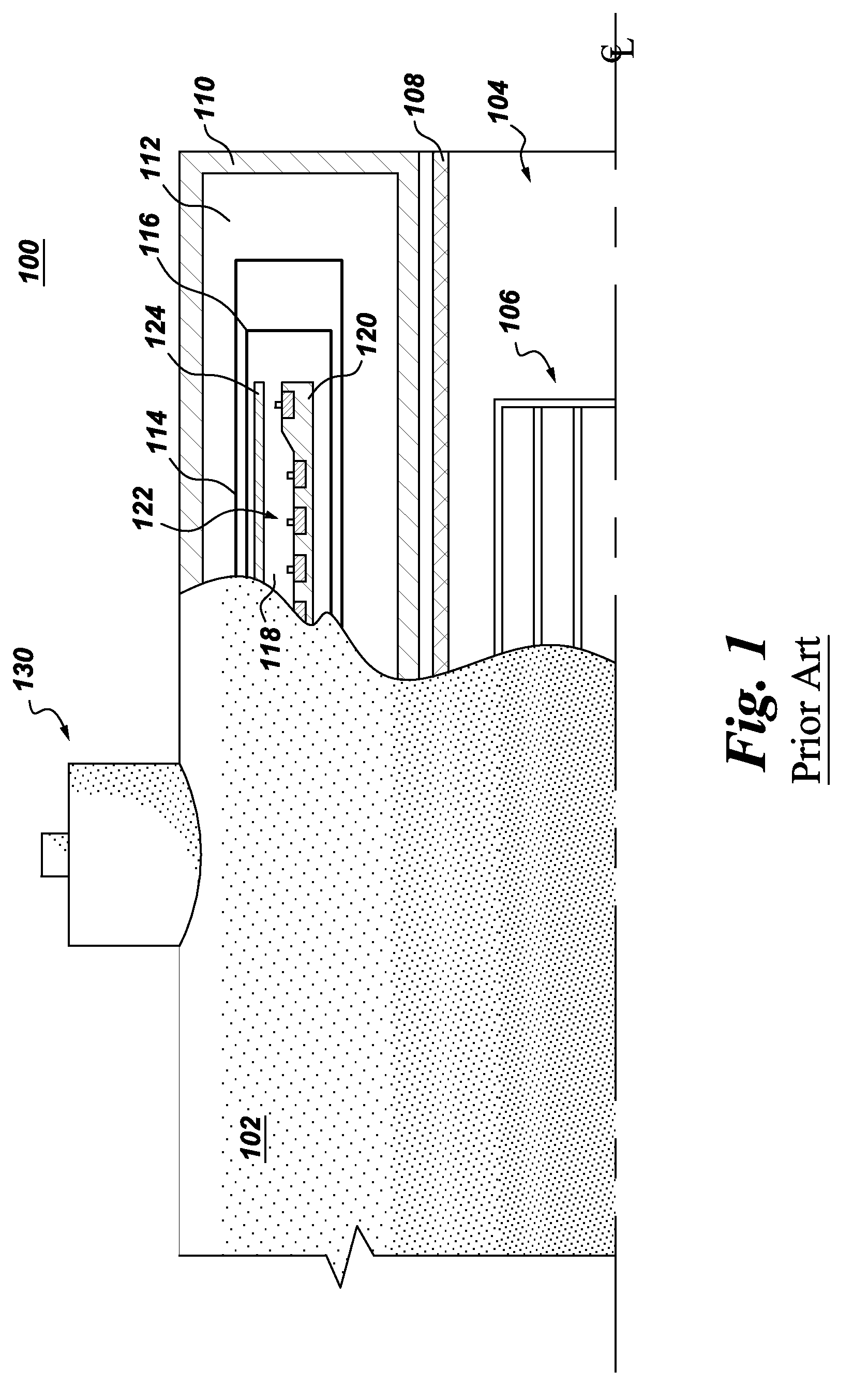
While a vertical orientation is preferred due to cryocooler durability issues, this orientation causes room height issues with the design.

Method used


Image

  • Apparatus and method for cooling a superconducting magnetic assembly
  • Apparatus and method for cooling a superconducting magnetic assembly
  • Apparatus and method for cooling a superconducting magnetic assembly

Examples


Embodiment Construction

[0018]Aspects of the present invention have been shown to offer advantages over previous methodologies of cooling superconducting magnets. The apparatus and method require no mechanical moving parts (e.g., no pumps, no external pressure fed supply system, no refrigeration “coldbox” for cryogen supply, no helium can-fed flow, etc.) in cooling the superconducting magnet. The cooling method is orientation-independent, which aids in the design and ultimate physical volume and footprint of the superconducting magnet assembly. Design integration of tubing into the existing superconducting magnet geometry is simplified. Further, hot spots that may arise can be cured by the pulsating slug flow provided by the pulsating heat pipe(s) employed under aspects of the present invention. The design offers other advantages in that it does not require costly helium bath cooling, nor is any cryogen lost during a quench. The proposed capillary tubing can withstand high pressures of several 100 bars. As...


PUM

PropertyMeasurementUnit
temperatureaaaaaaaaaa
volumeaaaaaaaaaa
pressuresaaaaaaaaaa

Abstract

A superconducting magnet assembly and method of cooling a superconducting magnet assembly. An embodiment of the method of manufacturing a superconducting magnet assembly includes: providing a housing configured about a vacuum reservoir; forming a coil former; surrounding the coil former with a thermal shield; locating the thermal shield in the vacuum reservoir; positioning a superconducting magnet about the coil former, wherein the superconducting magnet is configured about a central core to receive an object; providing a second vacuum reservoir having a cryogen reservoir therein; providing two two-phase heat transfer devices wherein each comprises tubing having an evaporator region and a condenser region; thermally connecting the evaporator region of one of the heat transfer devices with the coil former and/or the superconducting magnet and the evaporator region of the other two-phase heat transfer device with the thermal shield; and thermally connecting a cryocooler to the cryogen reservoir and to the condensing region of both heat transfer devices.

Description

CROSS-REFERENCE TO RELATED APPLICATIONS[0001]This application is related in some aspects to commonly owned U.S. application Ser. No. ______ (to be provided), entitled “APPARATUS AND METHOD OF SUPERCONDUCTING MAGNET COOLING”, assigned attorney docket number 226910-1, filed concurrently herewith, the entire contents of which are herein incorporated by reference.BACKGROUND OF THE INVENTION[0002]The present invention relates generally to the cooling of superconducting magnets and more particularly to an apparatus and method for cooling a superconducting magnetic assembly such as a magnetic resonance imaging (MRI) assembly.[0003]Various systems employ superconducting magnets to generate a strong, uniform magnetic field within which a subject, or as in the case of an MRI system a patient, is placed. Magnetic gradient coils and radio-frequency transmit and receive coils then influence gyromagnetic materials in the subject to provoke signals that can be used to form useful images. Supercond...

Claims


Application Information

Patent Timeline
Patent Type & Authority Applications(United States)
IPC IPC(8): G01R33/035H01L39/24H01L39/02
CPCG01R33/3804G01R33/3815H01F5/02Y10T29/49014H01F6/06H01F41/048H01F6/04G01R33/38
Inventor STAUTNER, ERNST WOLFGANG
Owner GENERAL ELECTRIC CO
Why Eureka
Try Eureka