Biological Signal Measuring Apparatus

a signal measuring and biological technology, applied in the field of biological signal measuring apparatus, can solve the problems of difficult to carry out the above method by oneself, unsuitable for continuous measurement of pulse waves, and the measured value can vary quite a bit, etc., to achieve high weight coefficient, weight coefficient, and weight coefficient

Active Publication Date: 2010-09-30
CITIZEN WATCH CO LTD
View PDF7 Cites 8 Cited by
  • Summary
  • Abstract
  • Description
  • Claims
  • Application Information

AI Technical Summary

Benefits of technology

[0065]By the present invention, a plurality of the periodic data that is a time interval of an oscillatory wave signal such as a pulse wave are collected and stored as a group signal that is a data group to be measured. The periodic data is compared with a predetermined value by a section discrimination part and classified into a plurality of sections such as a section of a short period, a section of a middle period, and a section of a long period. A weight coefficient is increased for the periodic data of a middle period, and a weight coefficient is decreased for the periodic data of a short period and the periodic data of a long period to calculate an oscillatory wave period weighted average value.
[0066]In other words, the proper periodic data that is most included in a section of a middle period is weighted with a high weight coefficient. On the other hand, the periodic data that includes a noise and that is included in a section of a short period or a section of a long period with a great deal is not removed at all and is weighted with a low weight coefficient.
[0067]Consequently, in handling a signal and a noise, a distinction is not made too sharp between a signal and a noise as 1 or 0, and a signal and a noise are individually weighted sensitively in detail. As a result, a reduction in the number of data to be measured does not cause a frequency band to be expanded, whereby it is possible to provide a biological signal measuring apparatus having a high degree of accuracy at a low cost.

Problems solved by technology

However, a certain level of skill is required for the above method, and it is hard to carry out the above method by oneself.
However, the direct counting system requires a time period of one minute for a measurement and is not suitable for a continuous measurement of a pulse wave.
As a result, a measured value can vary quite a bit unfortunately.
However, a total configuration of an apparatus for the electrocardiographic wave detection system has a tendency to be complicated, and the electrocardiographic wave detection system is not yet widely used as the general technology.

Method used


Image

  • Biological Signal Measuring Apparatus
  • Biological Signal Measuring Apparatus
  • Biological Signal Measuring Apparatus

Examples


embodiment 1

Descriptions of all Drawings for a First Embodiment: FIG. 1 and FIG. 8

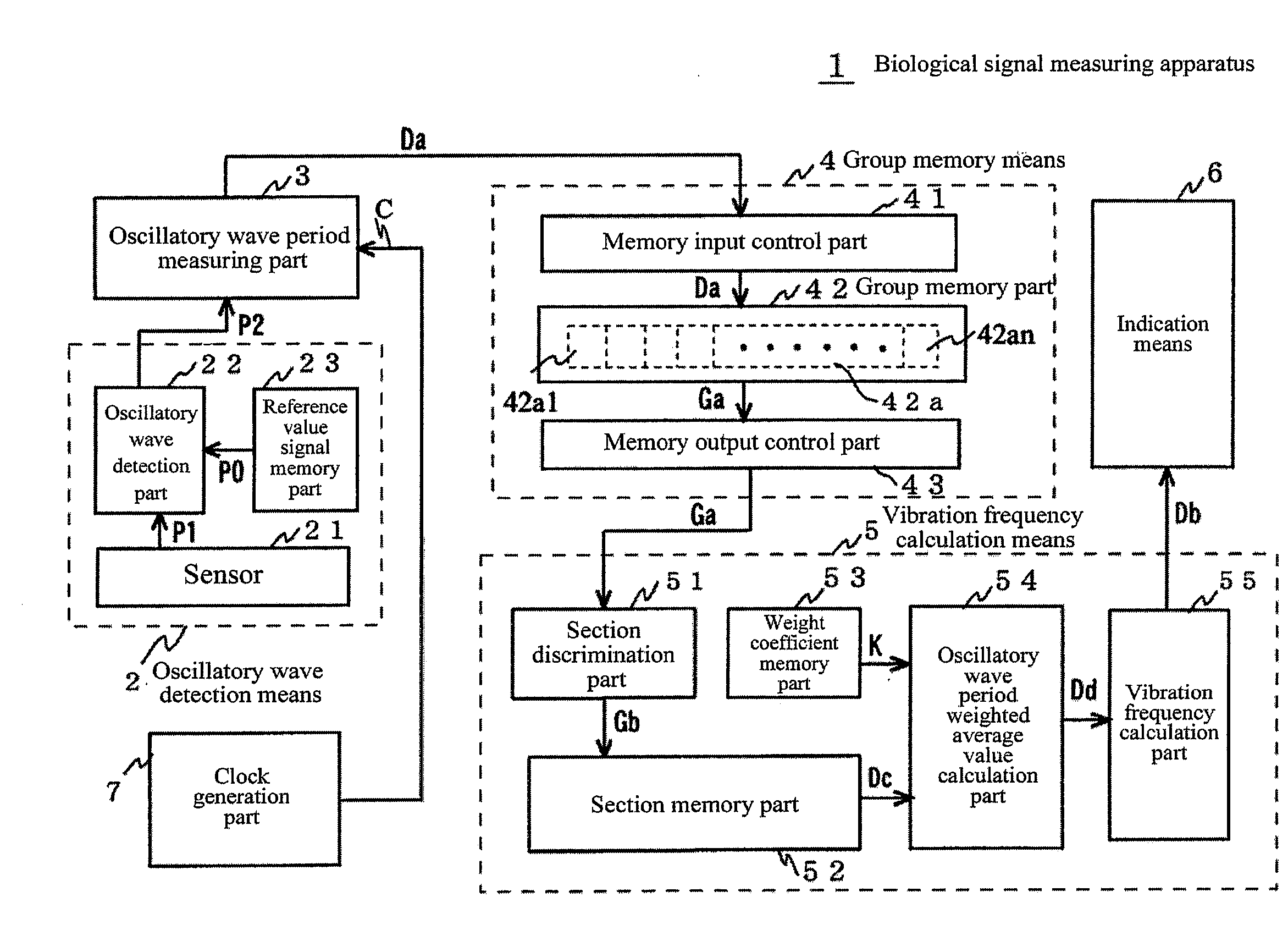
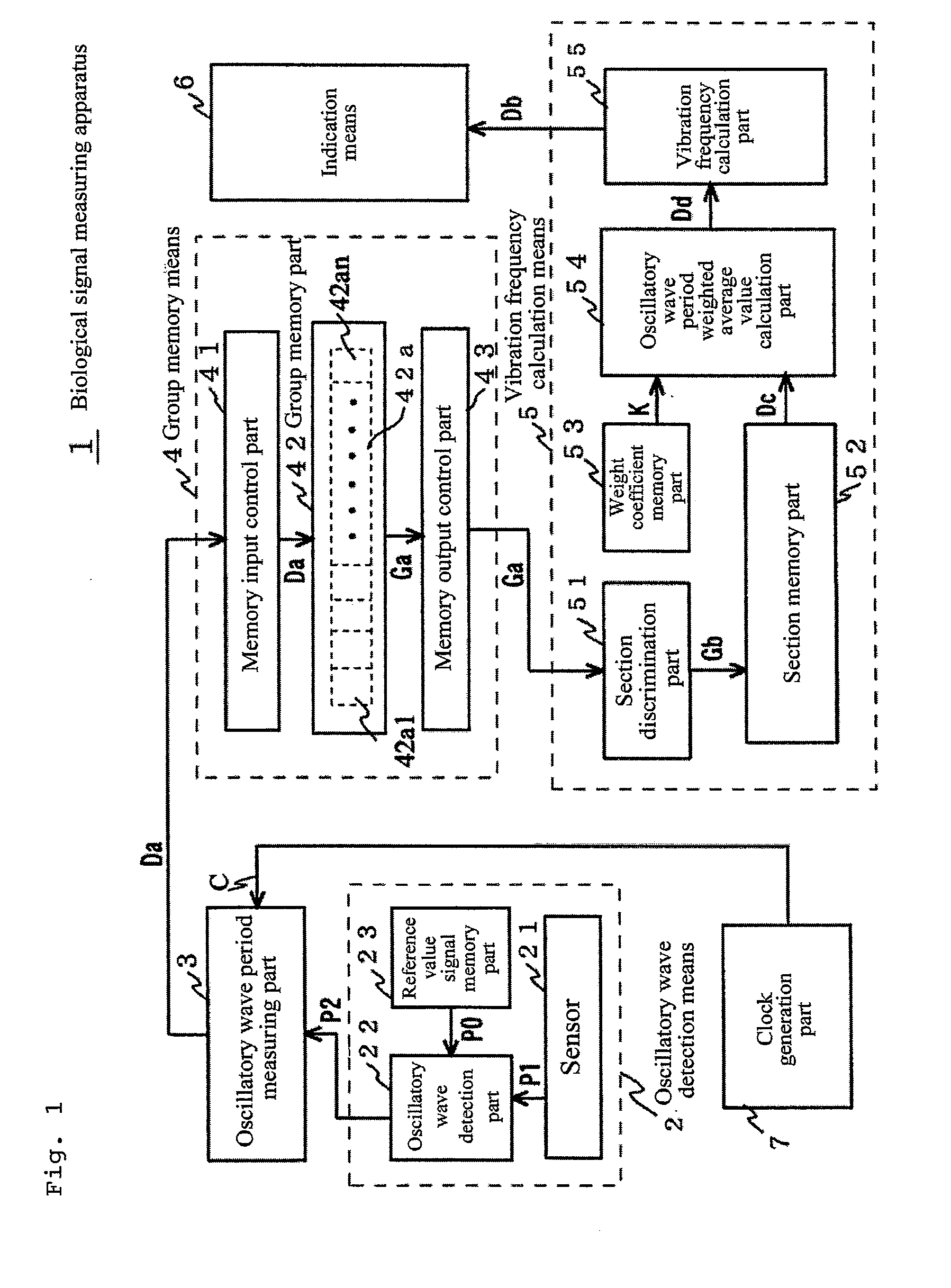
[0088]A first embodiment (example) of the biological signal measuring apparatus in accordance with the present invention will be described below in detail with reference to FIG. 1 and FIG. 8.

[0089]FIG. 1 is a functional block diagram, FIG. 8 is a waveform diagram of an oscillatory wave signal, and FIG. 9 is a table showing a numeric value example of an oscillatory wave signal.

[0090]A configuration of the first embodiment of the biological signal measuring apparatus in accordance with the present invention will be described below in detail with reference to FIG. 1 and FIG. 8.

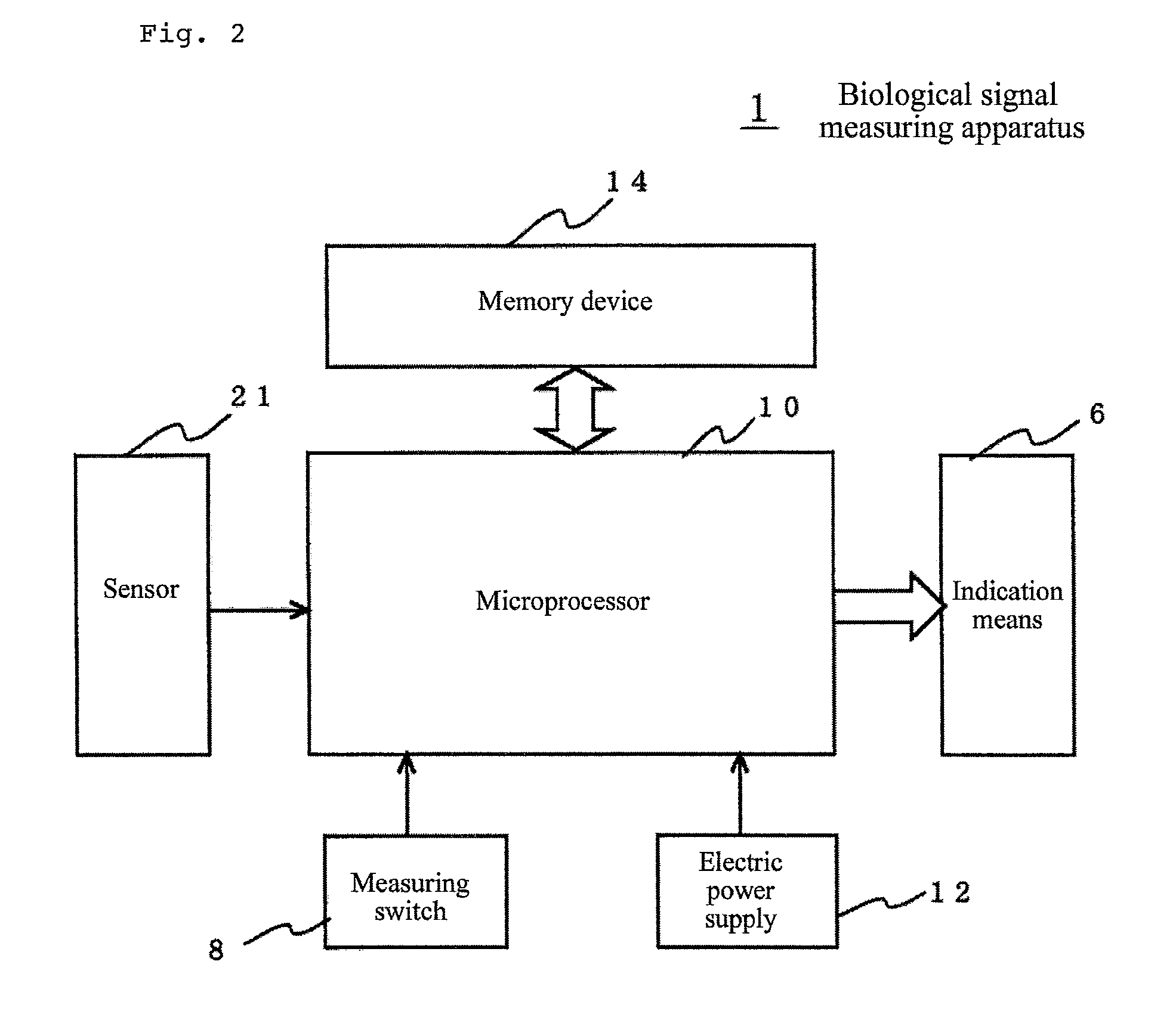
[0091]In FIG. 1, a biological signal measuring apparatus 1 is composed of an oscillatory wave detection means 2, an oscillatory wave period measuring part 3, a group memory means 4, a vibration frequency calculation means 5, an indication means 6, and a clock generation part 7.

Descriptions of the Oscillatory Wave Detection Means 2: FIG. 1 and F...

embodiment 2

Descriptions of all Drawings for a Second Embodiment: FIG. 10, FIG. 11, and FIG. 12

[0185]A second embodiment (example) of the biological signal measuring apparatus in accordance with the present invention will be described below in detail with reference to FIG. 10, FIG. 11, and FIG. 12. For the second embodiment, a configuration of a group memory means is different from that of the first embodiment. FIG. 10 is a block diagram for illustrating a group memory means for the second embodiment of the biological signal measuring apparatus in accordance with the present invention. FIG. 11 is a waveform diagram of an oscillatory wave signal for the second embodiment of the biological signal measuring apparatus in accordance with the present invention. FIG. 12 shows the results of sectioning the oscillatory wave signal of FIG. 11. For the descriptions, refer to the functional block diagram of FIG. 1 showing the first embodiment together with the above figures.

[0186]A difference of the second...


PUM


Abstract

A biological signal measuring apparatus that is provided with an oscillatory wave detection means, an oscillatory wave period measuring part, a group memory means that is configured to collect the periodic data and to store the periodic data as a group signal, and a vibration frequency calculation means. The vibration frequency calculation means is provided with a section discrimination part configured to compare the group signal with a predetermined value to carry out a section discrimination, a section memory part configured to store to a plurality of sections, a weight coefficient memory part configured to store a weight coefficient, and an oscillatory wave period weighted average value calculation part.

Description

TECHNICAL FIELD[0001]The present invention relates to a biological signal measuring apparatus that is configured to measure the number of repetitions per unit time for a periodic oscillatory wave that is generated by a biological body, such as an oscillatory wave that is caused by a pulsation of a biological heart or a breath and a physical oscillatory wave that is generated by walking.BACKGROUND ART[0002]A biological body generates a wide variety of oscillatory waves having a periodic property in a physiological function and an ecological activity of the biological body, and it is necessary to measure or monitor the number of repetitions per unit time, that is, the vibration frequency for the oscillatory waves more often than not.[0003]For instance, a sports medicine field recommends that a pulse, which is the most basic oscillatory wave that is generated by a biological body, is monitored in a successive manner in order to prevent an accident such as a heart failure and to improve...

Claims


Application Information

Patent Timeline
Patent Type & Authority Applications(United States)
IPC IPC(8): A61B5/103A61B5/332
CPCA61B5/02438A61B5/681A61B5/7264A61B5/024A61B5/7207A61B5/721A61B5/7203A61B5/0452A61B5/349
Inventor SHIMIZU, HIDEKI
Owner CITIZEN WATCH CO LTD
Why Eureka
Try Eureka