Shuffled LDPC decoding

a ldpc decoding and decoding technology, applied in the direction of code conversion, instruments, codes, etc., can solve the problems of complex processing of multiple diagonals, inability to solve ldpc codes containing “multi-diagonals”, and transmission errors, so as to reduce the cost of the known ldpc decoding architectur

Inactive Publication Date: 2010-09-30
ST ERICSSON SA
View PDF10 Cites 32 Cited by
  • Summary
  • Abstract
  • Description
  • Claims
  • Application Information

AI Technical Summary

Benefits of technology

[0004]It would be advantageous to provide an LDPC decoding architecture that is scalable, preferably can be used for several standardized systems with either single or multi-diagonal circulants. It would also be advantageous to reduce costs of the known LDPC decoding architectures.
[0012]In the architecture according to the invention, the symbol message (frequently referred to as the λnm message) is calculated in the linear domain (i.e. before the shuffler), contrary to prior art solutions where this calculation is carried out in the shuffled domain. This makes it possible without major redesign to produce an encoder suitable for single or multi-diagonal systems. Moreover, it enables cost-reduction. As described in the dependent claim 6, the sub-matrix may be a circulant, and the shuffler implemented as a barrel shifter.
[0014]By operating in the linear domain, dealing with such sub-matrices with multiple non-zero elements (e.g. multi-diagonals) is simplified. As described in the dependent claim 3, such multi-matrices can be handled in a simple iterative structure, where each time information from one associated check node message is combined with the intermediate result.
[0015]In an embodiment according to the invention, the LLR-BP algorithm is based on a min-sum algorithm and the LDPC encoder including correcting means for multiplying a value of a symbol message by a corrective factor α; and saturation means for restricting a value to a predetermined range; the correcting means and saturating means being arranged in between the first computation means and the barrel shifter. By performing the correction and saturation before the barrel shifter, the barrels shifter operates on a more restricted value range and can thus be implemented cheaper.
[0017]In an embodiment according to the invention, the LLR-BP algorithm is based on a min-sum algorithm; the second computation means including compression means for compressing check node messages and storing the check node messages in the second memory in a compressed form; and the first computation means including decompression means for decompressing check node messages read from the second memory. By storing the check node messages in a compressed form, costs are reduced. The architecture according to the invention can operate with both compressed as well as decompressed check node messages.

Problems solved by technology

In a transmission between a source and a receiver, some transmission errors may occur.
However, this architecture cannot solve LDPC codes containing “multiple diagonals”.
Processing of multiple diagonals is clearly more complicated.
However, this architecture is not scalable towards cheap instantiations which do not need to solve the “multiple diagonals”.

Method used


Image

  • Shuffled LDPC decoding
  • Shuffled LDPC decoding
  • Shuffled LDPC decoding

Examples


Embodiment Construction

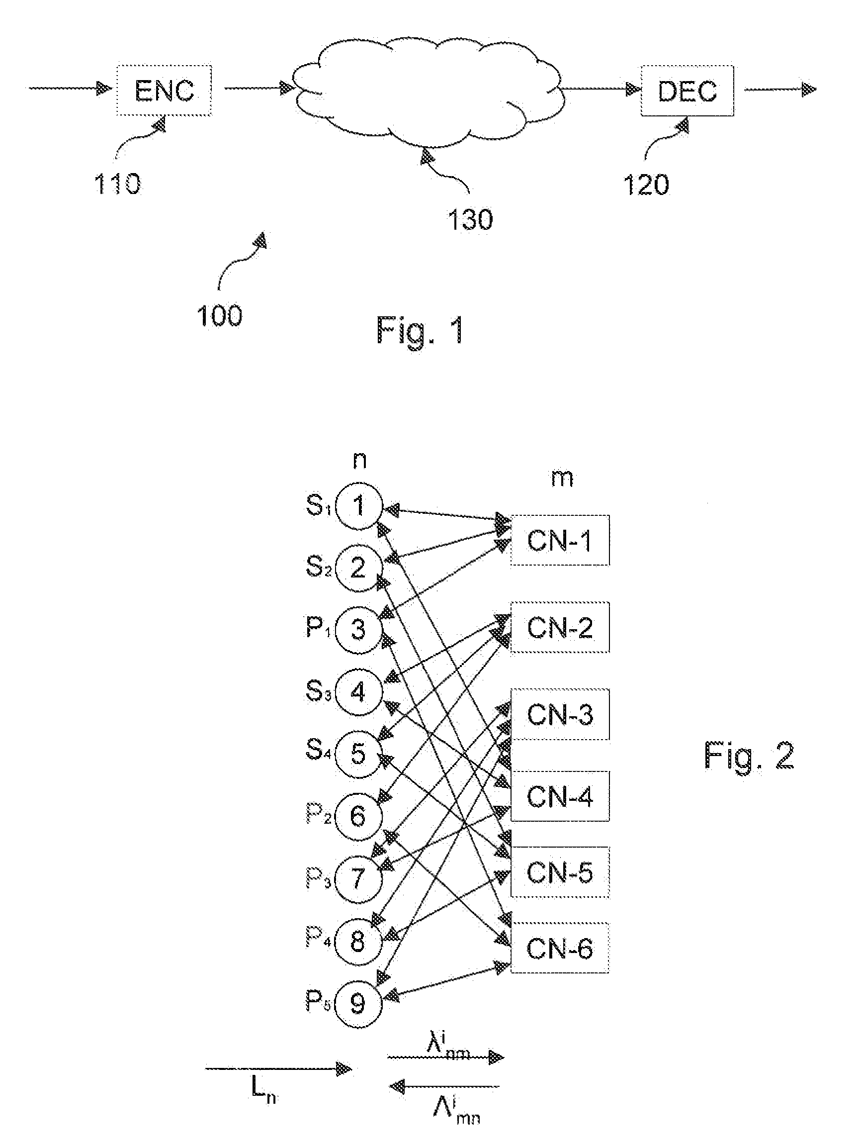
[0041]Where in the Figures same reference numerals are used, they represent the same functionality, unless specified differently. FIG. 1 shows a block diagram of an exemplary system 100 in which the invention may be used. The system includes an LDPC encoder 110 and an LDPC decoder 120. The encoded signal may be transmitted via a transmission medium 130, such as a wireless or wired network. It will be appreciated that the encoded signal may also be stored in a storage system such as a hard disk or optical storage. In this situation item 130 would represent the storage system. Many additional operations may occur which are not shown in FIG. 1, such as encrypting / decrypting, modulating / demodulating the signal, etc. Such operations are well-known and are not part of the invention.

[0042]LDPC encoding / decoding in itself is well-known. Here only a short description of the known aspects is given. In a simple example, it is the task of the encoder 110 to encode some binary information (usual...


PUM


Abstract

An LDPC decoder iteratively decodes an LDPC code represented by a parity check matrix H consisting of a plurality of circulants based on a Log-Likelihood Ratio Belief-Propagation algorithm. First computation means (1010) compute for a next iteration symbol messages λκm from a representation of a corresponding symbol value stored in a first memory 1005 and from check node messages Λmn from a previous iteration. A shuffler (1030) changes a sequence of the symbol message received from the first computation means (1010) in dependence on a position of the non-zero elements in a corresponding sub-matrix. Second computation N means (DP-O, DP-I, DP-D-I) compute the check node messages in dependence on symbol messages received from the barrel shifter and store a representation of the computed check node message in a second memory (1015). Third computation means (1020) update the representation of the symbol values in the first memory in dependence on output of the first and second computing means. The principle of “staggered” or “shuffled” LDPC decoding is used. One embodiment is designed for multi-diagonal circulants.

Description

FIELD OF THE INVENTION[0001]The invention relates to an LDPC decoder and LDPC decoding method.BACKGROUND OF THE INVENTION[0002]In a transmission between a source and a receiver, some transmission errors may occur. Error correcting codes can be used to detect and correct some of these errors. Low-Density Parity-Check (LDPC) Codes are a class of error correcting code: they are block codes (or equivalently parity-check codes) and are defined by a parity-check matrix H. They were introduced in 1963 by R. G. Gallager (in Gallager's Thesis, “Low-Density Parity-Check Codes”, 1963, MIT) in the case of LDPC codes over the Galois Field GF(2). The principle was generalized by Mackay in 1998 (in D. J. C Mackay, M. C. Davey, “Low Density Check Code over GF(q)”, Cavendish Laboratory, Cambridge, United Kingdom, 1998) over a Galois Field of higher cardinality, i.e. GF(rq) where r is a prime number. LDPC codes can be used in a variety of transmission systems, e.g. satellite communications, wireless ...

Claims


Application Information

Patent Timeline
Patent Type & Authority Applications(United States)
IPC IPC(8): H03M13/05G06F11/10
CPCH03M13/1114H03M13/6588H03M13/112H03M13/1122H03M13/1137H03M13/114H03M13/116H03M13/1165H03M13/1168H03M13/6527H03M13/6544H03M13/6566H03M13/658H03M13/6583H03M13/1117
Inventor DIELISSEN, JOHN
Owner ST ERICSSON SA
Why Eureka
Try Eureka