Vitreous silica crucible for pulling silicon single crystal

a technology of silicon single crystals and crucibles, which is applied in the direction of crystal growth process, crystal growth process, polycrystalline material growth, etc., can solve the problems of difficult temperature control of a reduced silicon melt, and high temperature of crucibles. , to achieve the effect of reducing deformation and less weigh

Active Publication Date: 2010-10-07
JAPAN SUPER QUARTZ CORP
View PDF10 Cites 15 Cited by
  • Summary
  • Abstract
  • Description
  • Claims
  • Application Information

AI Technical Summary

Benefits of technology

[0010]The present disclosure provides a vitreous silica crucible used for pulling silicon single crystal, which can allow a silicon raw material to be melted in a short time and improve production yield of silicon single crystals by a temporal change of an opaque vitreous silica layer.
[0012]In accordance with exemplary embodiments, relatively small bubbles contained in the opaque vitreous silica layer contribute to the thermal conductivity of a crucible at an initial pulling stage, and relatively large bubbles contained in the opaque vitreous silica layer are expanded through a long-term pulling process to thereby largely contribute to the warmth retaining property of the crucible at a later pulling stage. That is, at the initial stage of pulling silicon single crystal when a large amount of a silicon melt exists in the crucible, the crucible may have such a characteristic that the infrared transmittance is high and very susceptible to heat input. At the later stage of pulling silicon single crystal when the amount of the silicon melt is reduced, the vitreous silica crucible may have a characteristic that its warmth retaining property is enhanced.
[0013]In exemplary embodiments, the opaque vitreous silica layer may have a bubble diameter distribution in which a diameter difference between bubbles having a diameter less than 40 μm and bubbles having a diameter equal to or greater than 90 μm is less than 10%, desirably less than 5%. If the diameter difference is less than 10%, the balance between the small bubbles and large bubbles is good, and it is thus possible to provide a crucible excellent in both of heat-inputting property at the initial pulling stage and warmth retaining property at the later pulling stage. Moreover, if the diameter difference is less than 5%, the crucible which is more excellent in both of heat-inputting property and warmth retaining property may be provided.
[0015]In any configurations as illustrated above, it is possible to allow the upper part of the crucible to have less weight and also possible to substantially reduce deformation such as crookedness or buckling because the opaque vitreous silica layer contains a plurality of large-diameter bubbles.

Problems solved by technology

However, according to this structure, an infrared transmittance (thermal conductivity) is low at an initial stage of pulling silicon single crystal, and accordingly it takes much time for a silicon raw material to be melted in the crucible.
Furthermore, since the infrared transmittance becomes relatively higher at a later stage of pulling silicon single crystal, heat may be easily dissipated, warmth retaining property is insufficient, and thus temperature control of a reduced silicon melt is difficult.
When the temperature of the silicon melt is unstable, the production yield of silicon single crystals is decreased.
That is, at the initial stage of pulling silicon single crystal when a large amount of a silicon melt exists in the crucible, the crucible may have such a characteristic that the infrared transmittance is high and very susceptible to heat input.

Method used


Image

  • Vitreous silica crucible for pulling silicon single crystal
  • Vitreous silica crucible for pulling silicon single crystal
  • Vitreous silica crucible for pulling silicon single crystal

Examples


example 1

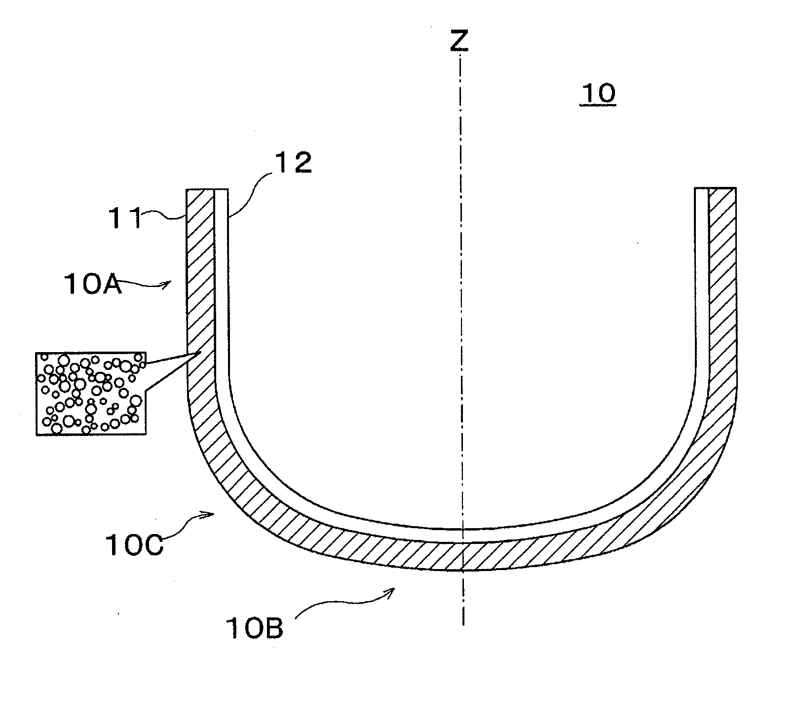
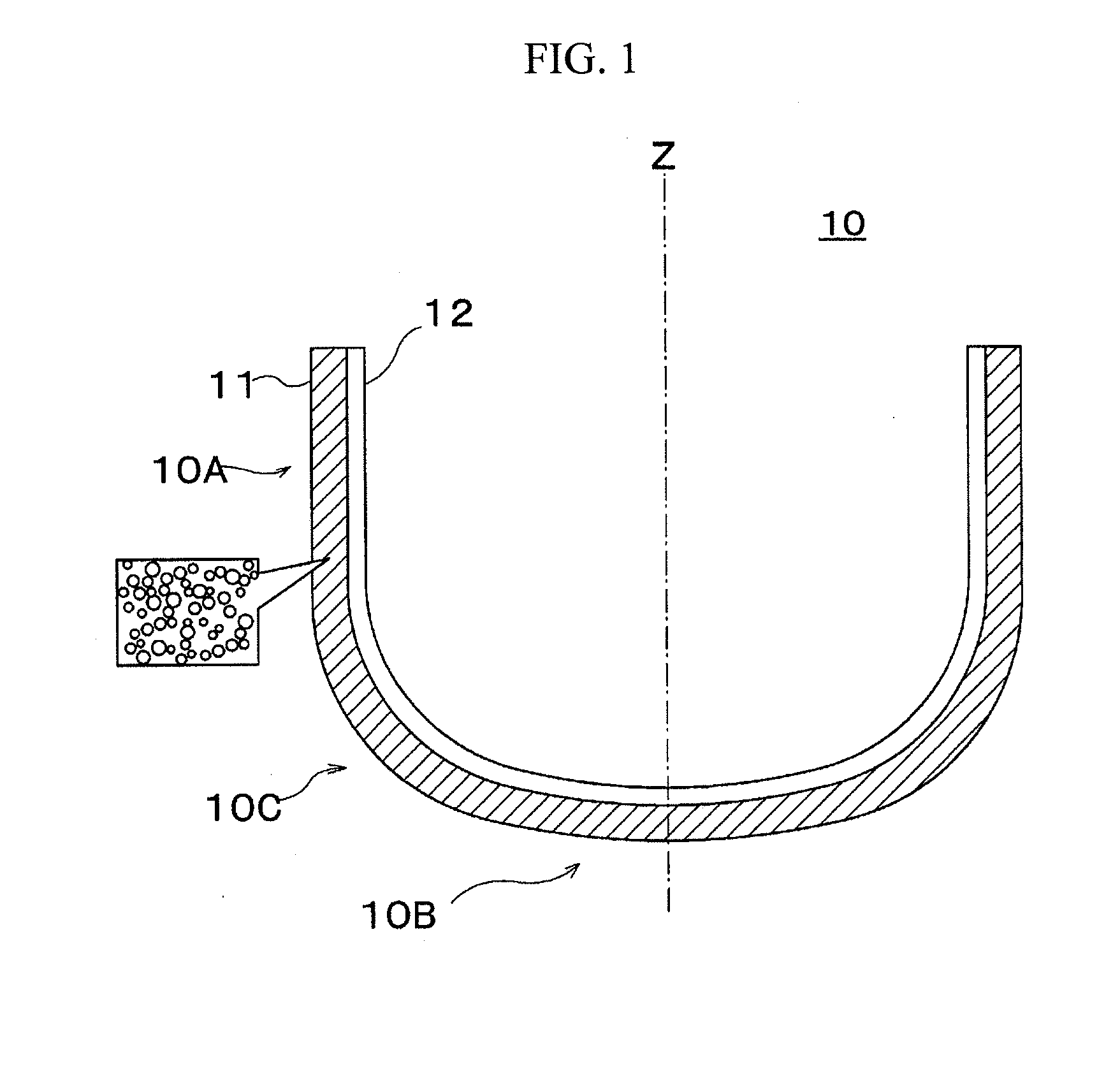
[0055]A vitreous silica crucible A1 with 32 inches (about 800 mm) in diameter was prepared. As shown in Table 1, a bubble diameter distribution of an opaque vitreous silica layer of the vitreous silica crucible was as follows: the content of bubbles having a diameter of less than 40 μm was 12.1%; the content of bubbles having a diameter of 40 μm or more and less than 90 μm was 72.9%; and the content of bubbles having a diameter equal to or more than 90 μm was 15.0%. The bubble diameter distribution was calculated by observing a cross-section of the vitreous silica crucible prepared using the same raw materials and conditions through a microscope. An infrared transmittance of the vitreous silica crucible before used was measured. The infrared transmittance E was measured in such a manner that an infrared power meter with a heat-receiving area of 1 cm2 was installed at a position 30 cm far from an infrared lamp having a wavelength band of 0.5 to 3.5 μm and a peak wavelength of 1.0 μm,...

example 2

[0059]A sample A2 of a vitreous silica crucible with 36 inches (about 900 mm) in diameter was prepared. As shown in Table 1, a bubble diameter distribution of an opaque vitreous silica layer of the vitreous silica crucible was as follows: the content of bubbles having a diameter of less than 40 μm was 16.4%; the content of bubbles having a diameter of 40 μm or more and less than 90 μm was 69.2%; and the content of bubbles having a diameter equal to or more than 90 μm was 14.4%. An infrared transmittance of the vitreous silica crucible before used was measured. An average infrared transmittance of the sidewall part, curved part and bottom part of the crucible was 63.0%.

[0060]Thereafter, a silicon single crystal ingot was pulled up under the same conditions of Example 1, and then an infrared transmittance of the vitreous silica crucible after used was measured. As shown in Table 1, an average infrared transmittance of the sidewall part, curved part and bottom part of the crucible was ...

example 3

[0061]A sample A3 of a vitreous silica crucible with 40 inches (about 1,000 mm) in diameter was prepared. As shown in Table 1, a bubble diameter distribution of an opaque vitreous silica layer of the vitreous silica crucible was as follows: the content of bubbles having a diameter of less than 40 μm was 13.3%; the content of bubbles having a diameter of 40 μm or more and less than 90 μm was 68.8%; and the content of bubbles having a diameter equal to or more than 90 μm was 17.9%. An infrared transmittance of the vitreous silica crucible before used was measured. An average infrared transmittance of the sidewall part, curved part and bottom part of the crucible was 61.4%.

[0062]Thereafter, a silicon single crystal ingot was pulled up under the same conditions of Example 1, and then an infrared transmittance of the vitreous silica crucible after used was measured. As shown in Table 1, an average infrared transmittance of the sidewall part, curved part and bottom part of the crucible wa...


PUM

PropertyMeasurementUnit
transparentaaaaaaaaaa
diameteraaaaaaaaaa
diameteraaaaaaaaaa

Abstract

Provided is a vitreous silica crucible for pulling silicon single crystals, which can melt a silicon raw material in a short time and improve production yield of silicon single crystals by temporal change of an opaque vitreous silica layer. The vitreous silica crucible includes an opaque vitreous silica layer(11) provided on an outer surface thereof and containing plural bubbles, and a transparent vitreous silica layer(12) provided on an inner surface and not containing bubbles substantially. The opaque vitreous silica layer(11) has a bubble diameter distribution in which the content of bubbles having a diameter of less than 40 μm is 10% or more and less than 30%, the content of bubbles having a diameter of 40 μm or more and less than 90 μm is 40% or more and less than 80%, and the content of bubbles having a diameter equal to or more than 90 μm is 10% or more and less than 30%. Relatively small bubbles contained in the opaque vitreous silica layer(11) contribute to the thermal conductivity of a crucible at an initial pulling stage, and relatively large bubbles contained in the opaque vitreous silica layer are expanded through a long-term pulling process to thereby largely contribute to the warmth retaining property of the crucible at a later pulling stage.

Description

CROSS-REFERENCE TO RELATED APPLICATION[0001]This application claims priority to Japanese Patent Application No. 2009-090518 filed on Apr. 2, 2009 and all the benefits accruing therefrom under 35 U.S.C. §119, the contents of which are incorporated by reference in their entirety.BACKGROUND[0002]The present disclosure relates to a vitreous silica crucible for pulling silicon single crystals, and more particularly, to a structure of an opaque vitreous silica layer in a vitreous silica crucible.[0003]A vitreous silica crucible is used to manufacture silicon single crystals. In Czochralski method (CZ method), polysilicon is put into a vitreous silica crucible, heated and melted to prepare a silicon melt, a seed crystal is then dipped into the silicon melt, and a silicon single crystal grows by gradually pulling up the seed crystal while rotating the crucible. To manufacture high-purity silicon single crystals for semiconductor devices, it is required that silicon single crystals should no...

Claims


Application Information

Patent Timeline
Patent Type & Authority Applications(United States)
IPC IPC(8): C30B15/10
CPCY10T117/10C30B15/10C30B35/002Y10T117/1032Y10T117/1004C30B29/06
Inventor KODAMA, MAKIKOKISHI, HIROSHIKANDA, MINORU
Owner JAPAN SUPER QUARTZ CORP
Why Eureka
Try Eureka