Solar receiver

Inactive Publication Date: 2010-10-07
BRIGHTSOURCE INDS ISRAEL
View PDF100 Cites 25 Cited by
  • Summary
  • Abstract
  • Description
  • Claims
  • Application Information

AI Technical Summary

Benefits of technology

[0014]In yet another aspect, the first portion may be connected to a source of liquid which is conveyed thereby. The second portion may be connected to a source of steam which is conveyed thereby. In another aspect, the second portion may be ada

Problems solved by technology

Because of this temperature differential, the tubes may be subject to excessive thermal stresses

Method used


Image

  • Solar receiver
  • Solar receiver
  • Solar receiver

Examples


Example

[0040]The invention provides an efficient system for the conversion of solar radiation to thermal energy and the creation of steam for powering a steam turbine electric power plant or the like, as well as components, articles of manufacture, and other technological improvements, and methods for using them.

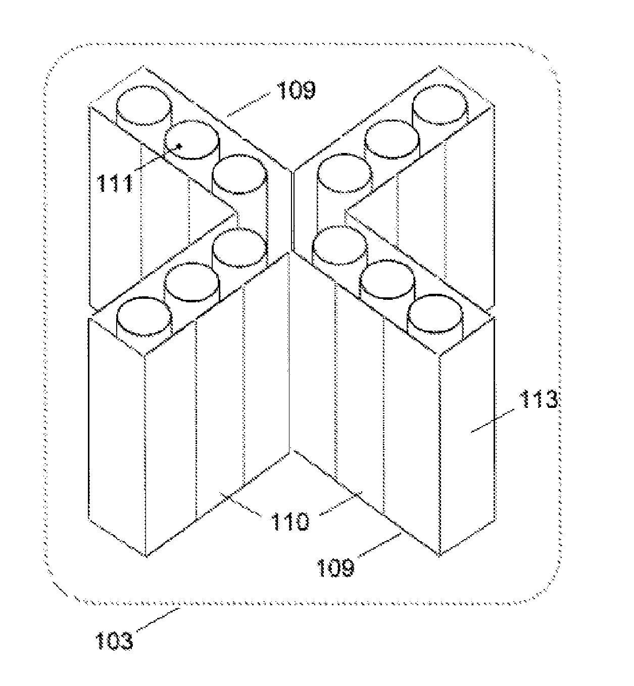
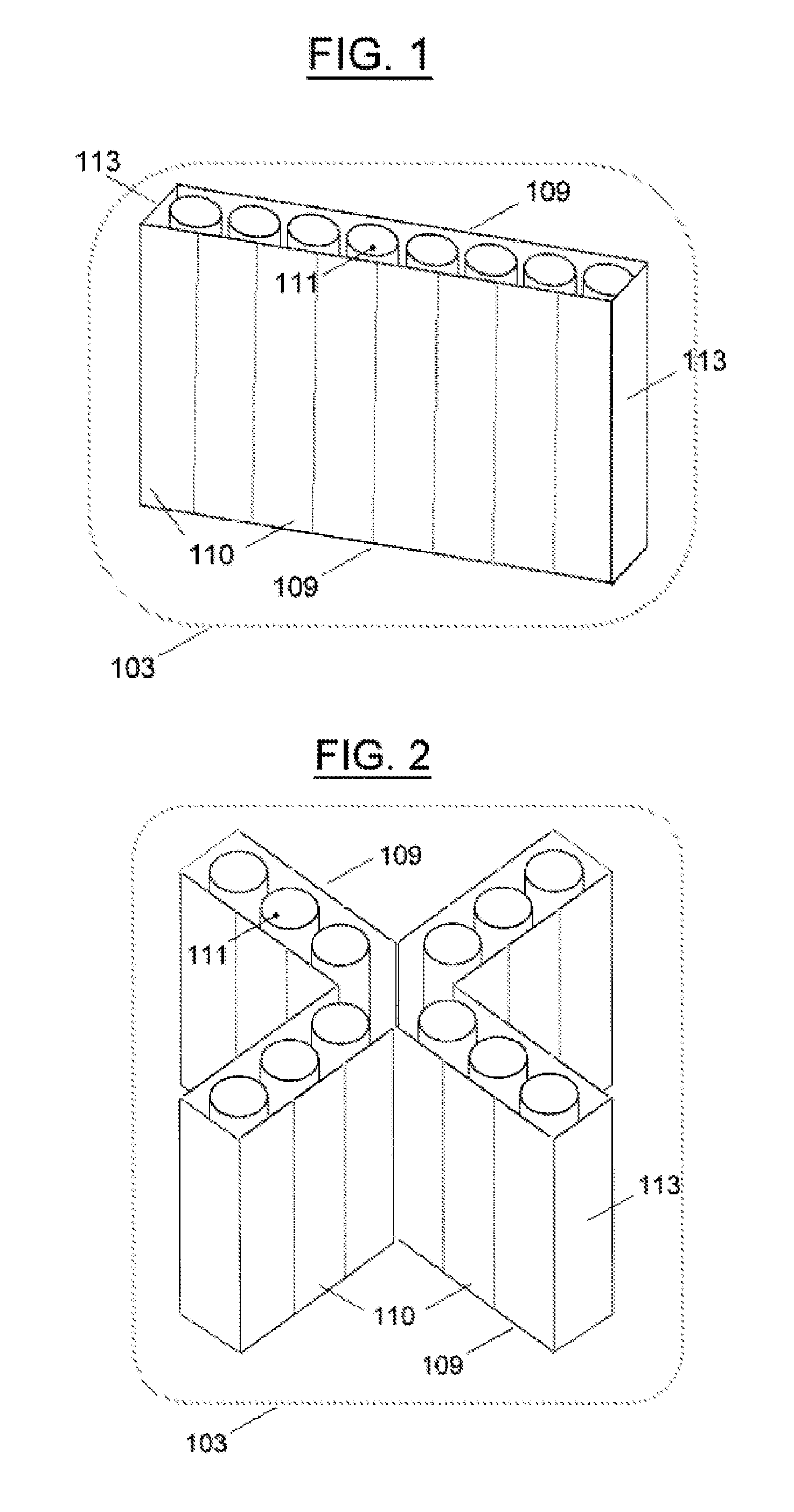
[0041]A solar receiver is a target for solar radiation reflected thereon by heliostats for the purpose of heating a fluid. The fluid is made to flow through a plurality of tubes or pipes in the receiver, which also includes conduits, pipelines, or the like, for providing ingress and egress to and from the receiver for the fluid.

[0042]The tubes may be positioned in a substantially vertical arrangement with multiple tubes conveying the fluid in parallel. Headers, manifolds and other piping arrangements may be provided to facilitate the transport of the fluid within the receiver and to and from the ingress and egress pipes. The receiver can be operated in the manner of a once-through ...


PUM


Abstract

A solar energy conversion system may include a receiver with a first heat transfer fluid channel having at least two opposite sides. Each side may present an external surface facing in a direction opposite to that of the external surface of the other opposite side. Each side may be configured to contact a heat transfer fluid carried in the first heat transfer fluid channel. A heliostat field may be configured to direct solar energy to each of the at least two opposite sides during the course of a day such that a thermal stress tending to bend the channel remains below a specified level.

Description

CROSS REFERENCE TO RELATED APPLICATIONS[0001]This application claims priority to U.S. Provisional Patent Application No. 60 / 951,970, filed on 26 Jul. 2007.FIELD OF THE INVENTION[0002]This invention relates generally to the conversion of solar radiation to thermal energy, for example in a solar electric power system.BACKGROUND[0003]A known type of solar receiver has a cylindrical shape and is built of tube panels deployed around the circumference of the boiler. An example of such a receiver in the prior art is disclosed in U.S. Pat. No. 4,485,803. In a cylindrical solar receiver, solar heat flux is absorbed by the exterior panels and transferred therefrom to the tubes on the interior side of each panel. The exterior-facing half of each tube will thereupon become hotter than the interior-facing half of each tube. Because of this temperature differential, the tubes may be subject to excessive thermal stresses and / or bending that could lead to subsequent damage of the solar receiver or ...

Claims


Application Information

Patent Timeline
IPC IPC(8): F24J2/38F24J2/24F24S10/70F24S50/20
CPCF24J2/0494Y02E10/47F24J2/1047F24J2/16F24J2/18F24J2/24F24J2/245F24J2/5406F24J2/5417F24J2002/0405F24J2002/1076F24J2002/4656F24J2002/5465Y02E10/41Y02E10/44F24J2/07F24S10/70F24S10/742F24S20/20F24S23/77F24S23/79F24S23/80F24S30/422F24S30/45F24S70/65F24S2020/18F24S2023/87F24S2030/135F24S2080/09Y02E10/40
Inventor KROIZER, ISRAELKAUFMANN, GABRIEL
Owner BRIGHTSOURCE INDS ISRAEL
Why Eureka
Try Eureka