Device for thin die detachment and pick-up

a technology which is applied in the field of detachment and pick-up of thin semiconductor dies, can solve the problems of die cracking or breaking, undesirable to apply the pyramidal-type pickup apparatus, and conventional pick-up tools using ejector pins may not be suitable for detaching thin dies from dicing films, etc., and achieves the effect of reducing the stress on the thin semiconductor chip

Active Publication Date: 2010-10-07
ASM ASSEMBLY AUTOMATION LTD
View PDF9 Cites 24 Cited by
  • Summary
  • Abstract
  • Description
  • Claims
  • Application Information

AI Technical Summary

Benefits of technology

[0014]It is thus an object of the invention to seek to provide an improved apparatus and method for separating a th

Problems solved by technology

It becomes a challenging task to detach a die from an adhesive film without damaging the die when the thickness of the die is reduced to below 4 mils (about 100 microns).
However, the die will crack or break when the process of deformation of the die also reaches the critical strength of the die.
Therefore, a conventional pick-up tool using ejector pins may not be suitable for detaching a thin die from a dicing film.
For this reason, it may also be undesirable to apply the pyramidal-type pickup apparatus for the separation of a thin semiconductor chip from a dicing film.
Also, productivity is low when using the slide-type pickup detachment tool due to the low moving speed of the slide.
A disadvantage of t

Method used


Image

  • Device for thin die detachment and pick-up
  • Device for thin die detachment and pick-up
  • Device for thin die detachment and pick-up

Examples


Embodiment Construction

[0025]The preferred embodiments of the invention will hereinafter be described with reference to the accompanying drawings.

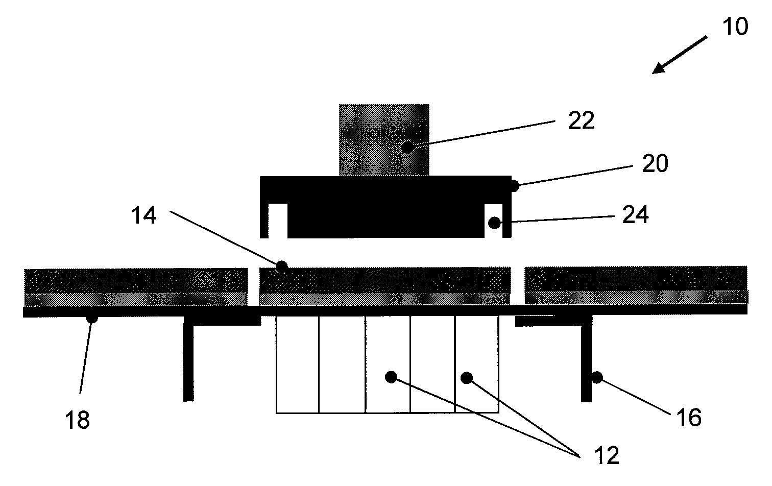
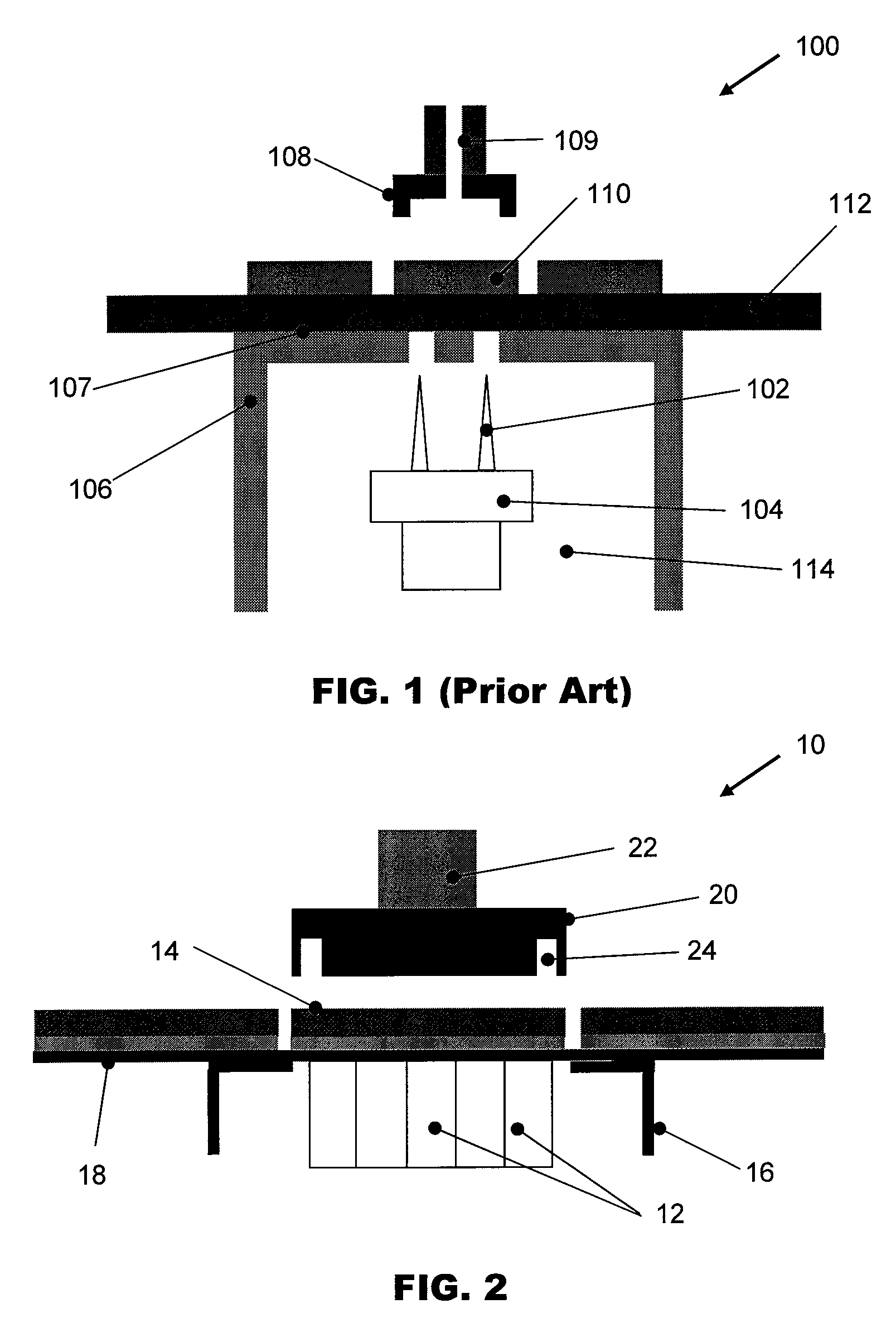
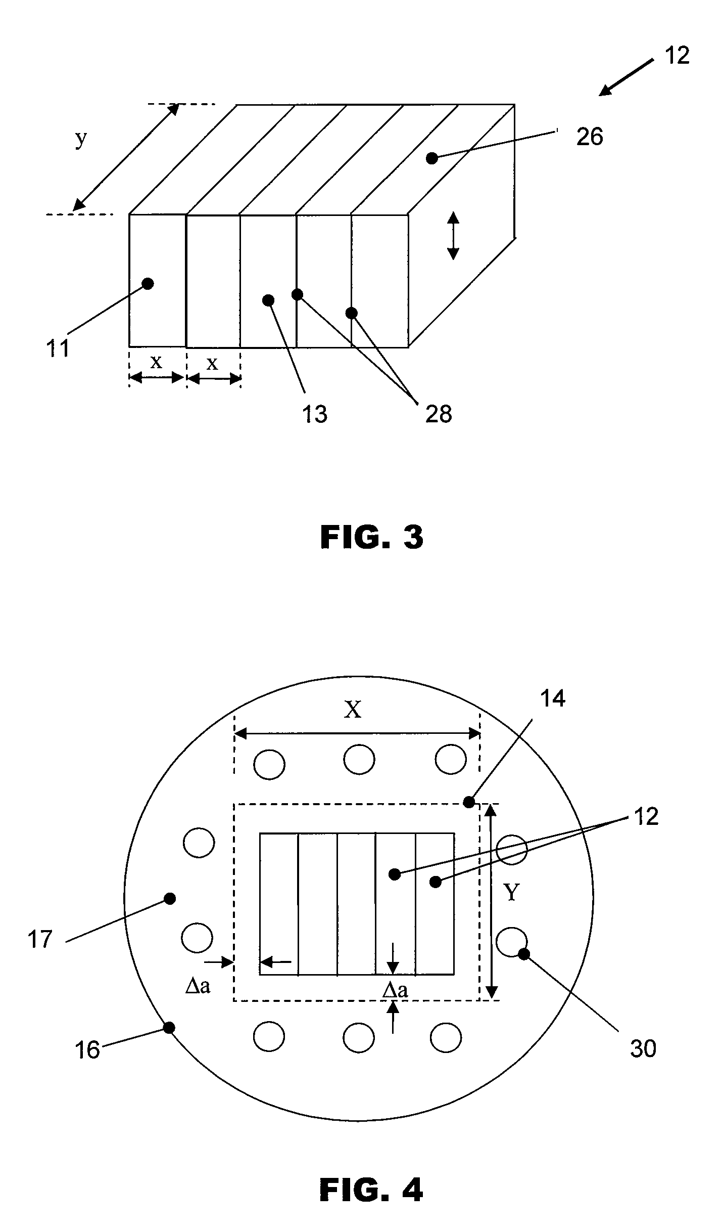
[0026]FIG. 2 is an illustration of a die detachment and pick-up tool 10 according to the preferred embodiment of the invention. A movable supporting plate unit 12 for delaminating a relatively thin die 14 is centrally located within an ejector cap 16. The movable supporting plate unit 12 comprises an intermediate movable supporting plate 13 and a plurality of outer movable supporting plates 11 on opposite sides of the intermediate movable plate 13. Each movable supporting plate 11, 13 may be of substantially the same dimensions as the other movable supporting plates. Each of these plates has a quadrilateral-shaped upper contact surface which is in the shape of a rectangle or square.

[0027]The movable supporting plates of the movable supporting plate unit 12 are arranged adjacent to one another such that the top surfaces of the movable supporting plates form a com...


PUM

PropertyMeasurementUnit
Lengthaaaaaaaaaa
Lengthaaaaaaaaaa
Distanceaaaaaaaaaa

Abstract

A die detachment device for delaminating a die which is mounted at a position on an adhesive film comprises a plurality of movable plates having quadrilateral-shaped contact surfaces which are arranged adjacent to one another. The plurality of movable plates comprises an intermediate movable plate and outer movable plates on opposite sides of the intermediate movable plate. The contact surfaces of the movable plates together form a combined contact surface for supporting the adhesive film at the position of the die, each movable plate being movable relative to the other movable plates towards and away from the die.

Description

FIELD OF THE INVENTION[0001]The invention relates to the handling of a semiconductor chip or semiconductor die during semiconductor assembly and packaging, and in particular to the detachment and pick-up of a thin semiconductor die from an adhesive film on which it is mounted.BACKGROUND AND PRIOR ART[0002]Typically, a wafer comprising a plurality of semiconductor dice are mounted on an adhesive film during singulation wherein each individual die is separated while it adheres to the adhesive film. Detaching and picking up of a die from an adhesive film is thus a common process involved in die bonding and flip chip bonding processes for assembling an electronic package. One trend for the development of high density electronic devices is to multiply its density on the same footprint by stacking up the dice comprised in an electronic package. The thickness of each die being stacked in the package has to be reduced in order to minimize the final height of the package.[0003]It becomes a c...

Claims


Application Information

Patent Timeline
IPC IPC(8): B23P19/04
CPCH01L21/67132Y10T156/1983H01L2221/68318H01L2221/68327H01L2221/68336Y10S156/941Y10S156/943Y10S156/931Y10S156/932Y10T156/1179Y10T156/1132Y10T156/1989Y10T156/1978Y10T156/1168Y10T156/1944H01L21/6836
Inventor CHAN, MAN WAIAU, YUK CHEUNGWONG, KWOK WAICHONG, CHI MING
Owner ASM ASSEMBLY AUTOMATION LTD
Why Eureka
Try Eureka