However, the solid oxide fuel cell has not been commercialized because the manufacturing cost is too high.
Considering multi-cell measurement, referring to S. C. Singhal,
Solid State Ionics, 135 (2000) 305 and K. Ahmed, J. Gamman and K. Foger,
Solid State Ionics, 152-153 (2002) 485, additional equipments are added to the
system to integrate multiple cells as a cell stack and the
system, which leads to very high cost.
The cell stack is assembled with time-consuming work, complicated elements, and high material cost.
Moreover, the system is susceptible to the quality of these elements so that it is difficult to identify the
manufacturing quality and explain the measured results to cause a mistake to mislead the research direction and hence extend the
time to market.
However, since the solid oxide fuel cell 50 is required to be attached with a
platinum conductive wire sintered thereon before electric characteristics are measured, related
processing steps are time-consuming and material cost is increased.
However, since the coefficient of
thermal expansion of
ceramic glue is not matched with that of the solid oxide fuel cell 50, cracks may appear in the solid oxide fuel cell 50.
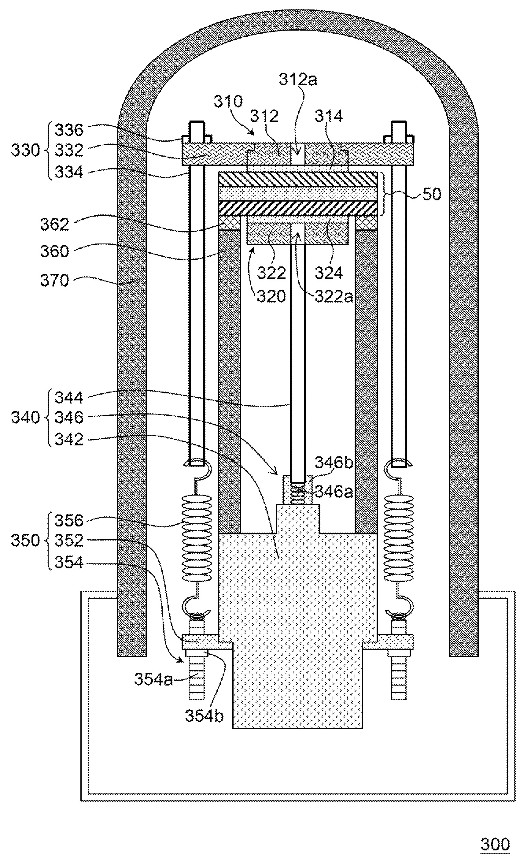
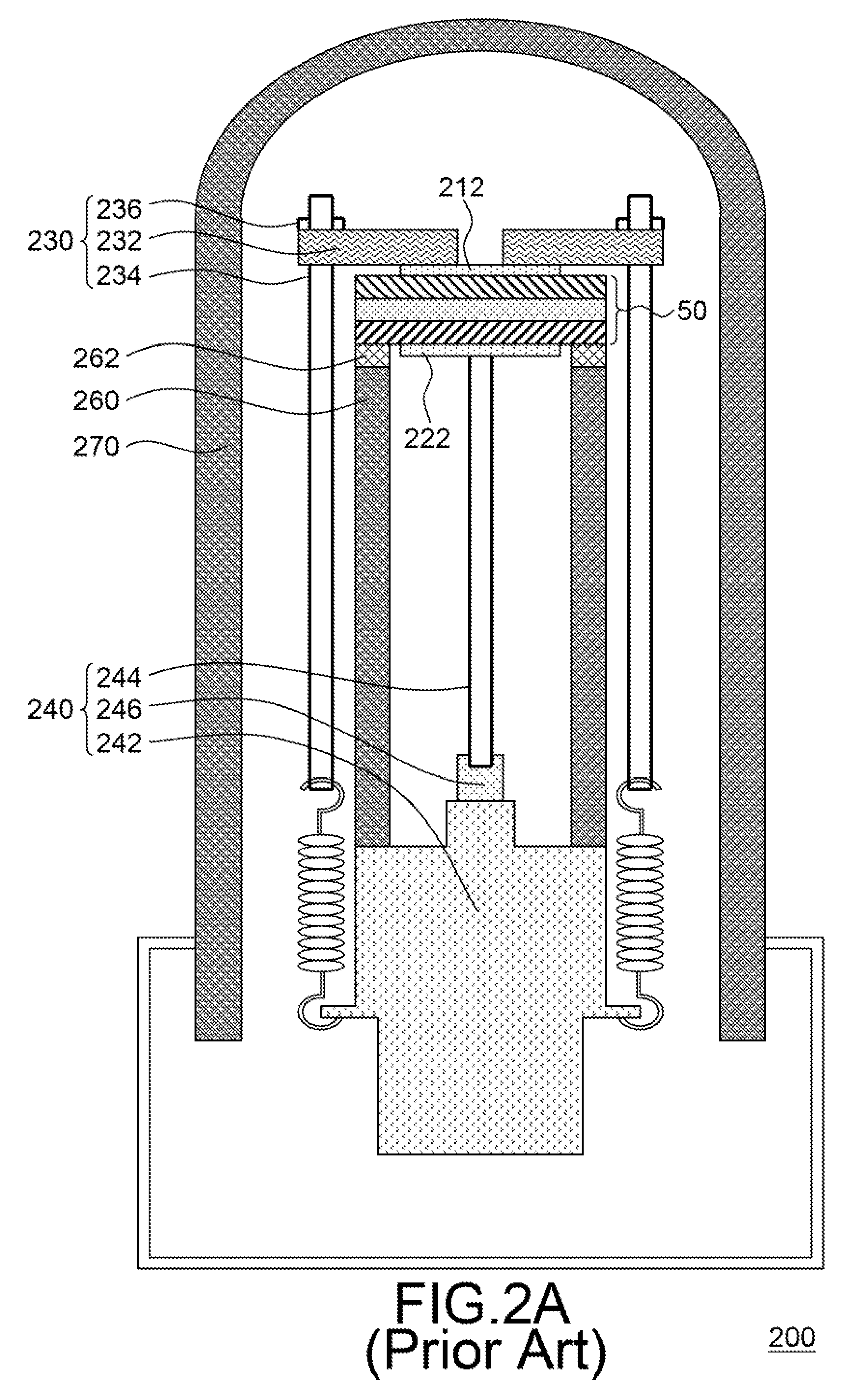
1. The contacts between the solid oxide fuel cell 50 and the first current collecting unit 210 and the second current collecting unit 220 determine the contact resistances that strongly influence the output power of the solid oxide fuel cell 50. For the second current collecting unit 220, only the second
platinum conductive mesh 222 is supported so that the contact area between the second current collecting unit 220 and the solid oxide fuel cell 50 is insufficient. Therefore, the output current is blocked and the cell performance is limited.
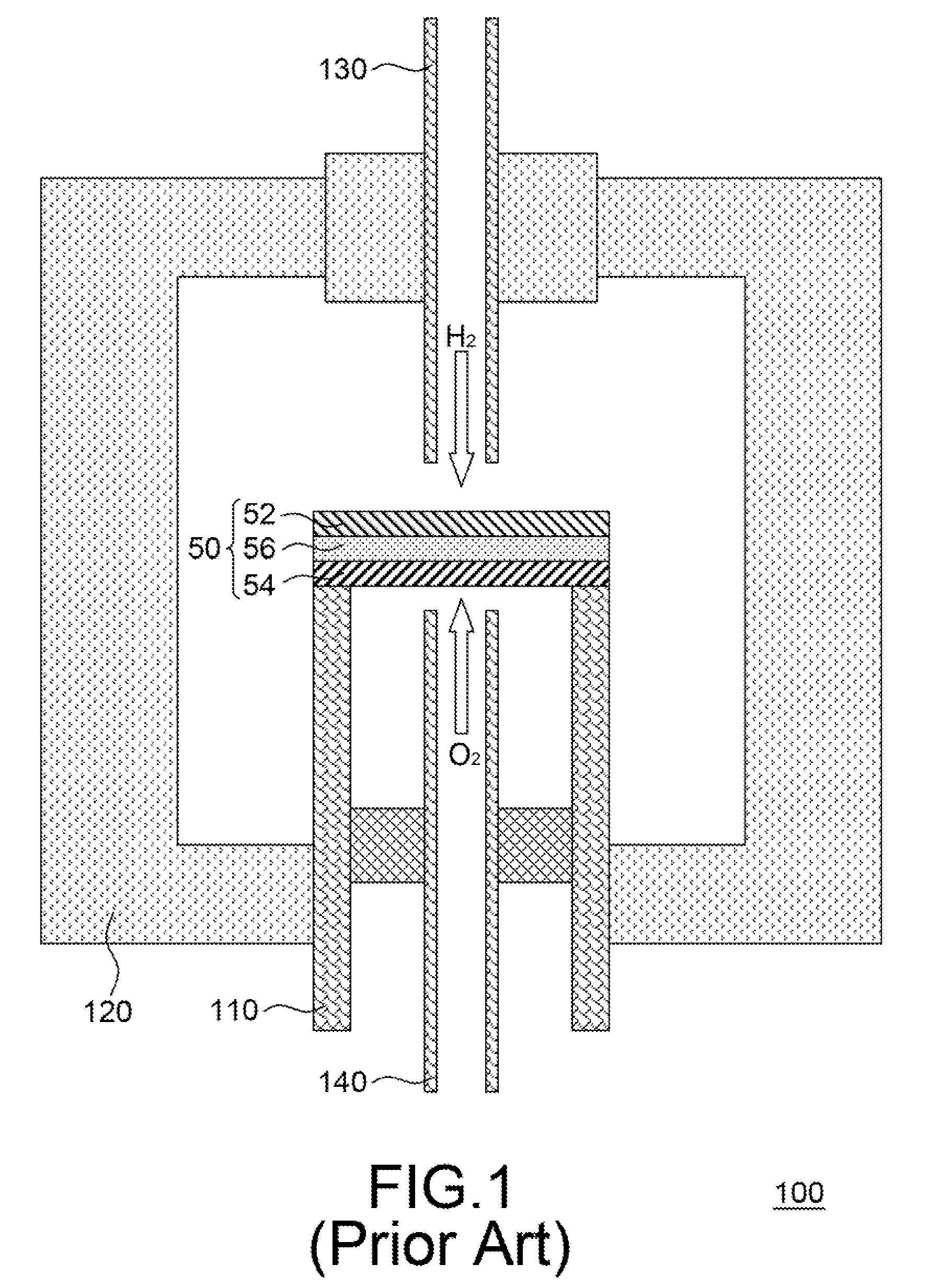
2. After
hydrogen H2 and
oxygen O2 flow from the first gas
pipe 280 and the second gas
pipe 290, the gas distribution is not uniform because there is no gas path. As a result, the energy generated by the solid oxide fuel cell 50 is not uniform and thermal stress occurs due to non-uniform temperature distribution, which leads to cracks in the solid oxide fuel cell 50.
3. The second
platinum conductive mesh 222 is often out of shape and destructed because the
ceramic shaft 244 supports the second platinum conductive mesh 222. Therefore, the second platinum conductive mesh 222 cannot be re-used. Moreover, if
ceramic shaft 244 is not disposed properly or obliquely supports the second platinum conductive mesh 222, the solid oxide fuel cell 50 may be damaged.
4. In the prior art, the pulling force of the spring 250 is a constant that cannot be adjusted. Therefore, when the thickness of the solid oxide fuel cell 50 varies, the applied pulling force from the spring 250 will be different, which leads to poor condition consistency of cell measurement. Moreover, in the prior art, the pulling force of the spring 250 is a constant. If the
mechanical strength of the tested solid oxide fuel cell 50 varies, it may cause damage to the solid oxide fuel cell 50 since the pulling force of the spring 50 is too large when solid oxide fuel cell 50 is installed or measured. On the contrary, if the pulling force of the spring 250 is too small, the first current collecting unit 210 and the second current collecting unit 220 cannot tightly contact the solid oxide fuel cell 50 to result in larger resistance. Moreover, since the base 242 is hooked by the spring 250, there is risk that the hook may be loosen so that the ceramic shaft 234 or even the solid oxide fuel cell 50 cracks due to collision. In this case, the solid oxide fuel cell 50 cannot be demounted and re-used.
5. The first gas
pipe 280 and the second gas pipe 290 are not equipped with a pressure meter so that the
anode pressure and the
cathode pressure cannot be monitored. Therefore, gas leakage occurs due to unbalanced pressure and error in measurement results from non-uniform
reactive gas concentrations.

