Electronic control unit and method of manufacturing the same
a control unit and electronic technology, applied in the direction of electrical apparatus construction details, electrical connection formation of printed elements, transportation and packaging, etc., can solve the problems of disadvantageous large manufacturing cost and disadvantageous low heat radiation performance, and achieve the effect of reducing man-hours and short time of period
- Summary
- Abstract
- Description
- Claims
- Application Information
AI Technical Summary
Benefits of technology
Problems solved by technology
Method used
Image

Examples
first embodiment
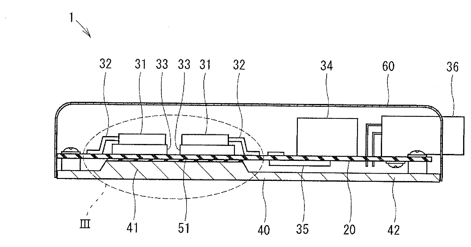
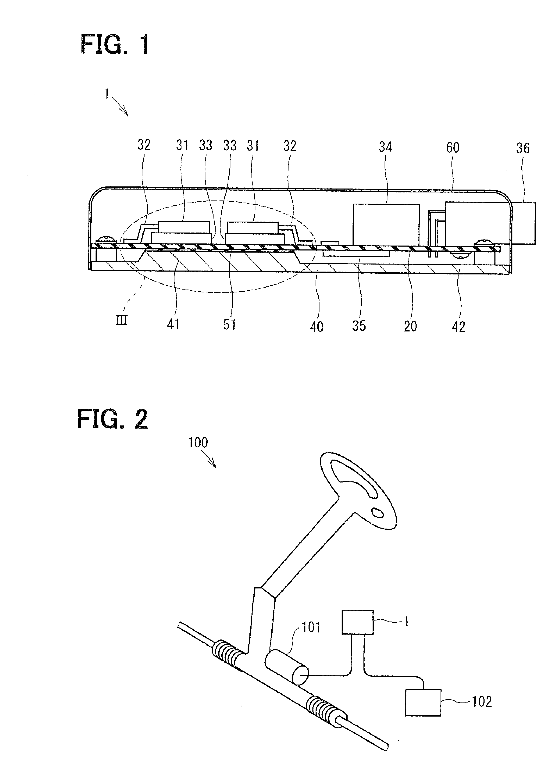
[0040]An electronic control unit 1 of a first embodiment is illustrated below. As shown in FIGS. 1 and 2, the electronic control unit 1 is used in an electric power-assisted steering system 100, and performs drive control of a motor 101 for generating a steering assistance force, based on a steering torque signal and a vehicle speed signal.
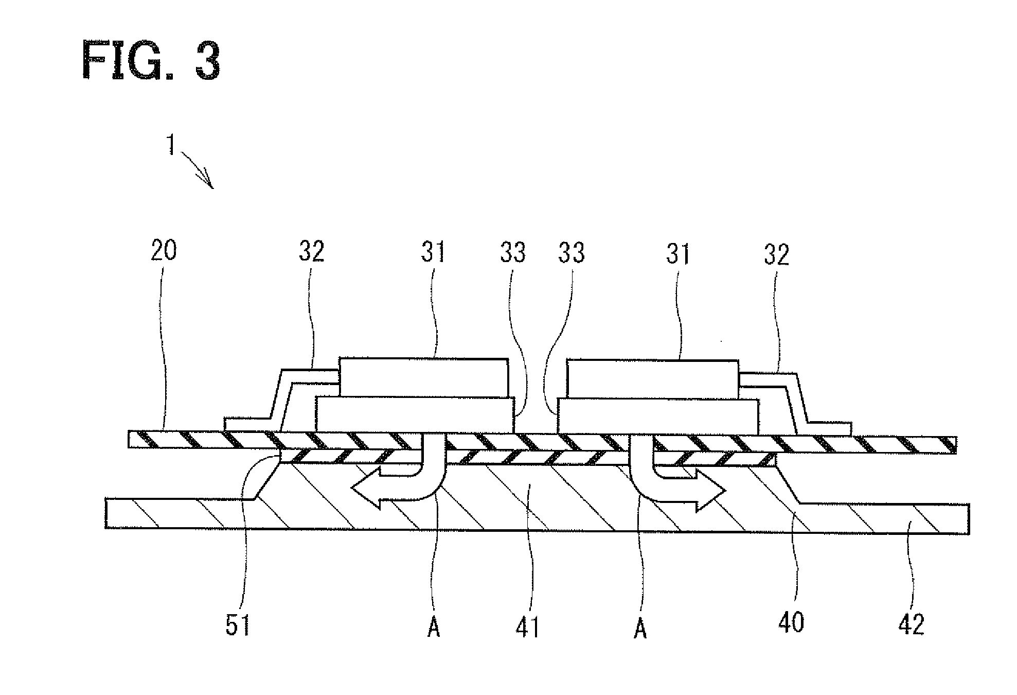
[0041]The electronic control unit 1 includes a resin board 20, a heat sink 40, and a cover 60. On the resin board 20, multiple electronic components are mounted. The resin board 20 is fixed to the heat sink 40. The cover 60 covers the resin board 20 fixed to the heat sink 40. The resin board 20 is, for example, a printed wiring board such as a FR-4 printed wiring board and the like. The heat sink 40 is an example of first heat radiation means and a first heat radiator.
[0042]The FR-4 printed wiring board is composed of a fiberglass cloth and an epoxy resin binder. The electronic components surface-mounted on the resin board 20 includes a power MOSF...
second embodiment
[0059]An electronic control unit 2 according to a second embodiment is illustrated below with reference to FIG. 6. In the second embodiment, the resin board 20 has an opening 21. The projection part 41 of the heat sink 40 is inserted into the opening 21. An insulating heat-radiation sheet 51 is disposed between the projection part 41 and the resin board 20. The insulating heat-radiation sheet 51 is in direct contact with the metal base 33 of the power MOS 31 and the heat sink 40. When a large current for driving the motor 101 flows through the power MOS 31, the heat generated by the power MOS 31 is conducted from the power MOS 31 to the insulating heat-radiation sheet 51 and the heat sink 40 and is radiated to the air, as shown by the arrow “B” in FIG. 6.
[0060]In the second embodiment, a thermal resistance of the heat radiation path for conducting and radiation the heat generated by the power MOS 31 is given as “Tz+Th”. Thus, the electronic control unit 2 of the second embodiment ha...
third embodiment
[0061]An electronic control unit 3 according to a third embodiment is illustrated below with reference to FIG. 7. The electronic control unit 3 of the third embodiment includes a second heat sink 66 and a heat radiation grease 71 in addition to a first heat sink 40. The second heat sink 66 is located on an opposite side of the power MOS 31 from the resin board 20. The heat radiation grease 71 fills a gap between the second heat sink 66 and the power MOS 31, thereby forming a second heat radiation path for conducting and radiation the heat generated by the power MOS 31. Distance of the gap between the second heat sink 66 and the power MOS 31 is set to a predetermined distance that causes substantially no stress on the power MOS. The second heat sink 66 is an example of second heat radiation means and a second heat radiator. The heat radiation grease 71 is an example of second heat conduction means and a second heat conductor.
[0062]When a large current for driving the motor flows thro...
PUM
| Property | Measurement | Unit |
|---|---|---|
| Temperature | aaaaa | aaaaa |
| Thickness | aaaaa | aaaaa |
| Heat | aaaaa | aaaaa |
Abstract
Description
Claims
Application Information
 - R&D
- Intellectual Property
- Life Sciences
- Materials
- Tech Scout
- Unparalleled Data Quality
- Higher Quality Content
- 60% Fewer Hallucinations
Browse by: Latest US Patents, China's latest patents, Technical Efficacy Thesaurus, Application Domain, Technology Topic, Popular Technical Reports.
© 2025 PatSnap. All rights reserved.Legal|Privacy policy|Modern Slavery Act Transparency Statement|Sitemap|About US| Contact US: help@patsnap.com