Process for preparing turbine blades or vanes for a subsequent treatment, and associated turbine blade or vane

a technology of turbine blades and vanes, which is applied in the direction of machines/engines, mechanical equipment, liquid fuel engines, etc., can solve the problems of uncoated parts of peripheral surfaces also being ground, and their final dimensions changing

Inactive Publication Date: 2010-10-07
SIEMENS AG
View PDF7 Cites 10 Cited by
  • Summary
  • Abstract
  • Description
  • Claims
  • Application Information

AI Technical Summary

Benefits of technology

[0007]According to the invention, the first part of the object is achieved by a process in which a covering strip is fitted to at least one peripheral surface to form a plug connection. Therefore, it is a basic concept of the invention for the peripheral surfaces of the endplate(s) to be protected with the aid of covering strips, which are each held on the turbine blade or vane by means of a plug connection. The plug connection allows simple yet secure fixing of the covering strip in the region of the peripheral surfaces. The covering strip protects the peripheral surfaces from being sprayed with coating material during the coating operation. Should overspray, i.e. coating of part of the peripheral surfaces, occur, this overspray can be removed following the coating operation by grinding with the covering strip still attached, in which case the covering strip then protects the uncoated part of the peripheral surfaces. This significantly reduces the risk of the size dropping below the required final dimensions.

Problems solved by technology

However, it is virtually inevitable that coating material will also reach those parts of the peripheral surfaces of the endplates which are adjacent to the hot-gas side, i.e. that some overspray, as it is known, will occur.
This presents the risk of uncoated parts of the peripheral surfaces also being ground, with the result that their final dimensions change.

Method used


Image

  • Process for preparing turbine blades or vanes for a subsequent treatment, and associated turbine blade or vane
  • Process for preparing turbine blades or vanes for a subsequent treatment, and associated turbine blade or vane
  • Process for preparing turbine blades or vanes for a subsequent treatment, and associated turbine blade or vane

Examples


Embodiment Construction

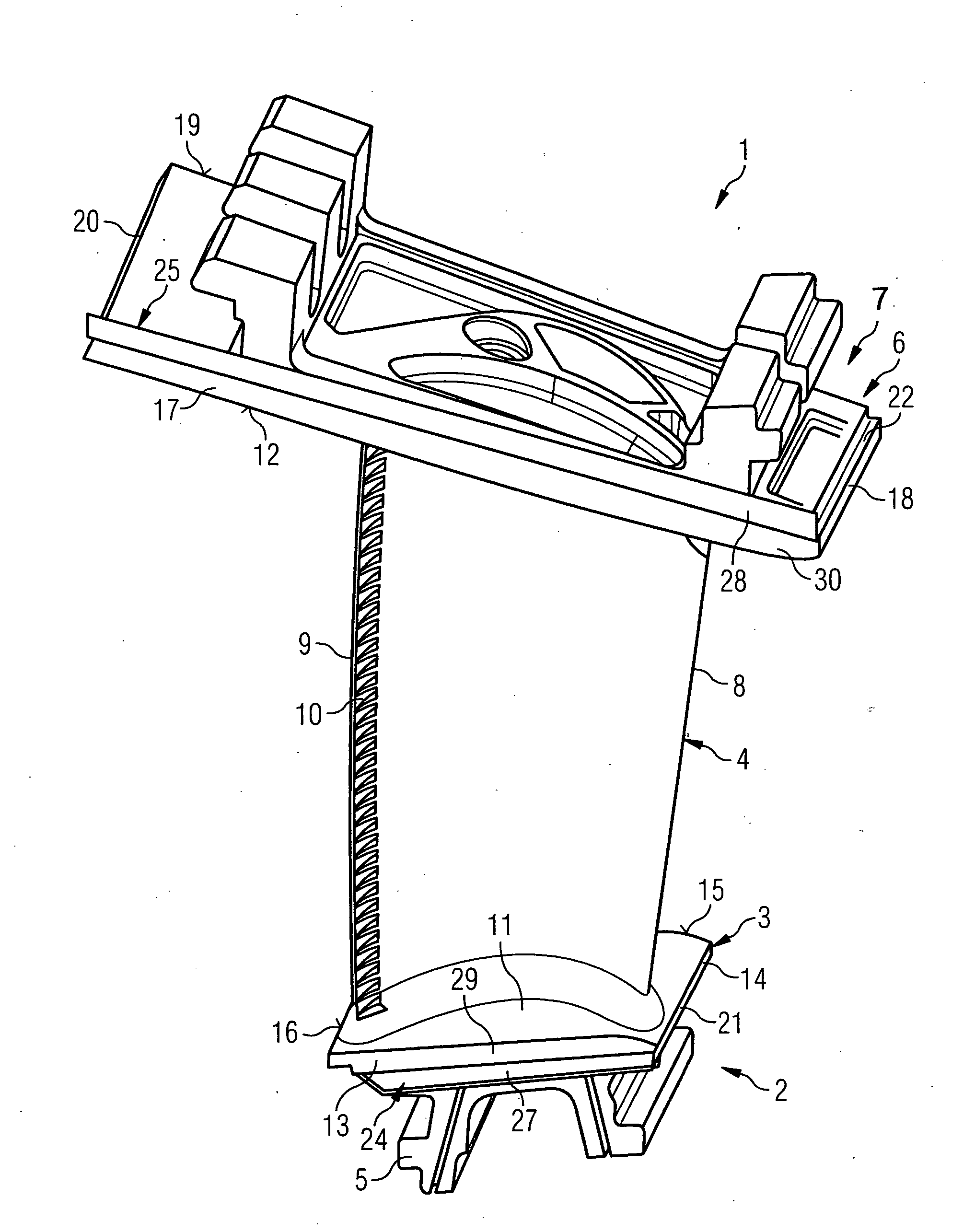
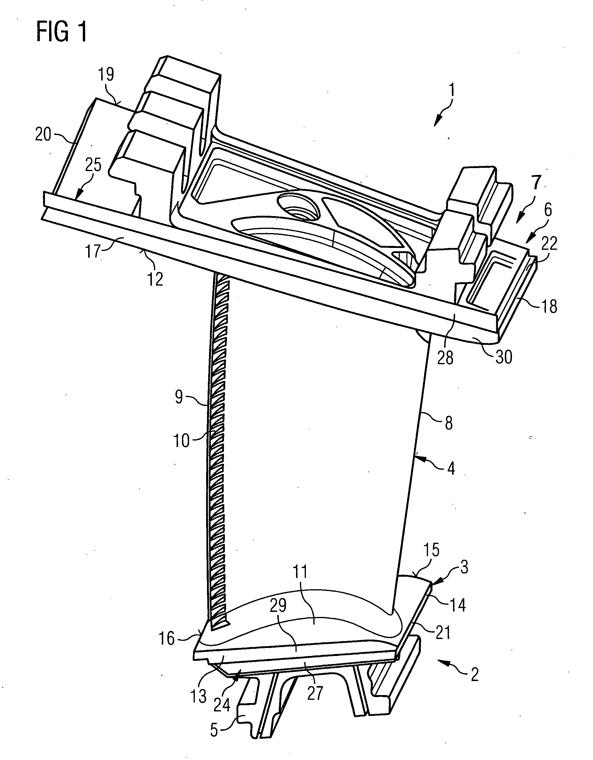
[0024]The guide vane 1 illustrated in FIG. 1 is intended for a turbomachine onward. This may be a gas turbine for an aircraft or a power plant for power generation, a steam turbine or a compressor.

[0025]The guide vane 1 has, in succession along its extent a securing region 2, an adjoining root plate 3, an airfoil 4 and a head part 5 which adjoins the vane tip and has a head plate 6 adjacent to the airfoil 4. The head part 5 is not present if the turbine blade or vane is configured as a rotor blade.

[0026]In the securing region 2 there is a blade root 7, which is used to secure the guide vane 1 to a disk (not shown). The vane root 7 is in this case designed as dovetail root. Other configurations, such as a fir-tree or hammerhead root, are also possible. The airfoil 4 has a leading edge 8 and a trailing edge 9 for a medium which passes through the turbomachine, flowing past the airfoil 4.

[0027]Conventional vanes consist, for example, of solid metallic materials, in particular superallo...


PUM

PropertyMeasurementUnit
angleaaaaaaaaaa
lengthaaaaaaaaaa
depthaaaaaaaaaa

Abstract

Process for preparing turbine blades or vanes for a subsequent treatment, for example the application of a coating and/or a material-removing operation, wherein the turbine blade or vane has an airfoil, which is delimited at at least one end by an endplate with peripheral surfaces, wherein at least one of the peripheral surfaces is at least partially covered prior to the treatment of the turbine blade or vane. In the process a covering strip is fitted onto at least one peripheral surface to form a plug connection.

Description

CROSS REFERENCE TO RELATED APPLICATIONS[0001]This application claims priority of European application No. 06000401.7 EP filed Jan. 10, 2006, which is incorporated by reference herein in its entirety.FIELD OF INVENTION[0002]The invention relates to a process for preparing turbine blades or vanes for a subsequent treatment, for example the application of a coating and / or a material-removing operation, wherein the turbine blade or vane has an airfoil, which is delimited at at least one end by an endplate with peripheral surfaces, wherein at least one of the peripheral surfaces is at least partially covered prior to the treatment of the turbine blade or vane. The invention also relates to a turbine blade or vane having an airfoil, which is delimited at at least one end by an endplate that has a hot-gas side facing the airfoil and adjoining peripheral surfaces.BACKGROUND OF INVENTION[0003]To improve their temperature and / or abrasion resistance, turbine blades or vanes, such as guide vane...

Claims


Application Information

Patent Timeline
Patent Type & Authority Applications(United States)
IPC IPC(8): F01D5/14B21D53/78F04D29/38
CPCC23C4/121C23C4/127Y10T29/49336F01D25/285Y02T50/67C23C4/185C23C4/123C23C4/134Y02T50/60
Inventor BOZDOGAN, HALISLADRU, FRANCIS-JURJENMULLER, JEANREYMANN, HELGESCHUSCH, MANUEL
Owner SIEMENS AG
Why Eureka
Try Eureka