
Methods and compositions for reducing wear of surfaces in contact with one another

a technology of surfaces and compositions, applied in the field of machining, can solve the problems of increased heat generation, reduced quality, heat generation, wear, etc., and achieve the effect of reducing wear

Active Publication Date: 2010-10-07
HOWARD UNIVERSITY +1
View PDF1 Cites 13 Cited by
  • Summary
  • Abstract
  • Description
  • Claims
  • Application Information

AI Technical Summary

Benefits of technology

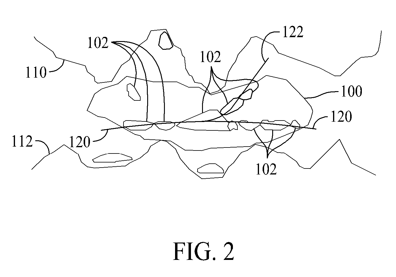
[0008]In one aspect, a method for reducing wear between two surfaces in sliding contact with one another is provided. The method includes introducing nanoparticles between the two surfaces, in a quantity and composition that results in shear lines being generated within at least one agglomerated wear particle. These agglomerated wear particles are generated between the two surfaces as a result of the sliding contact between the surfaces. By subjecting the agglomerated wear particles to at least one load, using at least one of the two surfaces, such that the agglomerated wear particles disassemble along the shear lines into multiple smaller wear particles, allowing for protected contact between the two surfaces.
[0009]In another aspect, a method for reducing wear between two surfaces in sliding contact with one another is provided. The method includes using nanoparticles to destabilize agglomerated wear particles that build up between the two surfaces as a result of the sliding contact, and causing the destabilized, agglomerated wear particles to break down into smaller pieces, allowing for protected contact between the two surfaces.

Problems solved by technology

Many processes are known where friction from a first metal device engaging a second metal device produces heat, wear, deformation, and surface blemishes.
In many of these applications, the wear resulting from the sliding engagement between the two devices eventually results in reduced quality, increased heat generation and a corresponding reduction in process speed or reduced energy efficiency.
While the accumulation and agglomeration of wear particles at the sliding interface and their adverse effects on friction and wear are known, the means for breaking down wear agglomerates has not been well considered.

Method used


Image

  • Methods and compositions for reducing wear of surfaces in contact with one another
  • Methods and compositions for reducing wear of surfaces in contact with one another
  • Methods and compositions for reducing wear of surfaces in contact with one another

Examples


Embodiment Construction

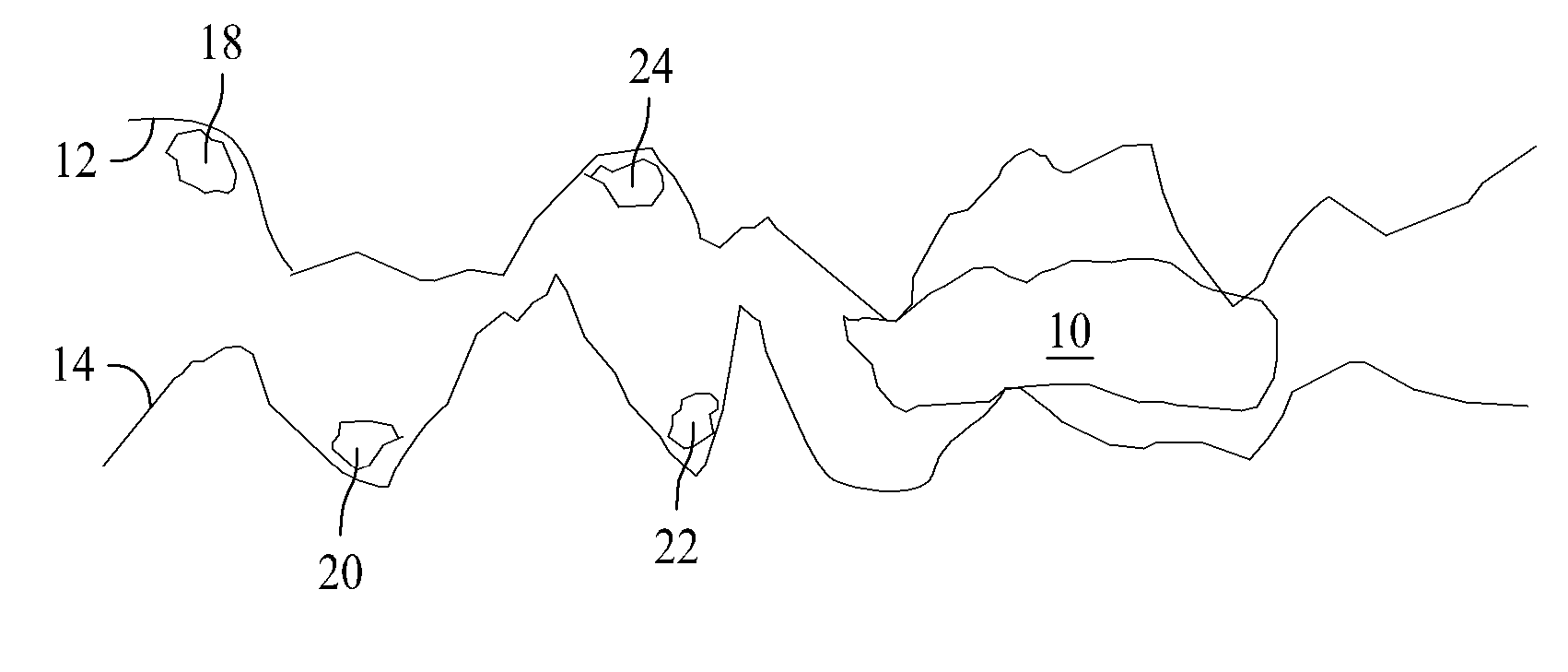
[0017]The embodiments described herein relate to methods and compositions for reducing mass loss of either or of both surfaces when those two surfaces are in sliding contact with one another. Generally, the surfaces are metal, such as a drill bit and a component on which the drill bit is operating. However, the embodiments are certainly applicable in applications where one or both of the surfaces are not metal. The reduction in the loss of mass occurs through the destabilization of agglomerated wear particles that are generated during the sliding contact, or rubbing, between the two items or surfaces. In other embodiments, the agglomerated wear particles may be referred to as a “solid film” which may have a relatively higher aspect ratio that is different from substantially spherical.

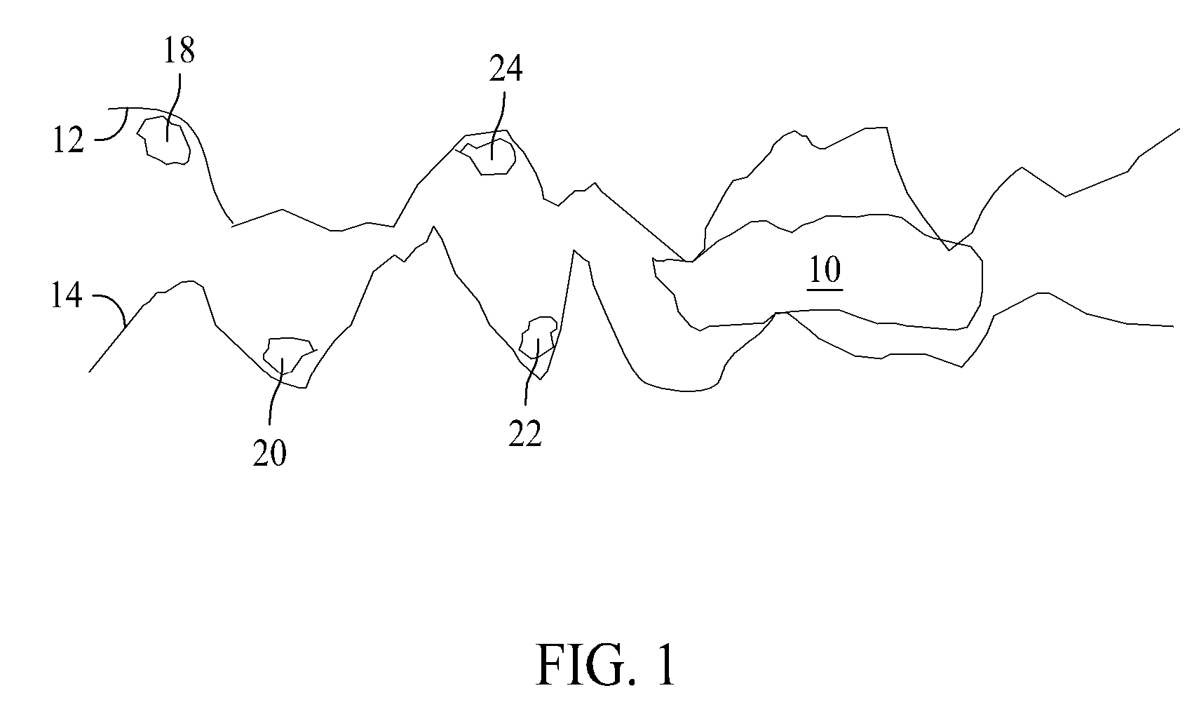
[0018]FIG. 1 is a prior art illustration of an agglomerated wear particle 10 between two surfaces 12 and 14 that are in sliding contact with one another. FIG. 1 is a microscopic view which illustrates t...


PUM

PropertyMeasurementUnit
particle sizeaaaaaaaaaa
volumeaaaaaaaaaa
output poweraaaaaaaaaa

Abstract

A method for reducing wear between two surfaces in sliding contact with one another includes introducing nanoparticles between the two surfaces in an amount and having a composition that results in shear lines being generated within at least one agglomerated wear particle that is generated between the two surfaces as a result of the sliding contact, and subjecting the agglomerated wear particles to at least one load, using at least one of the two surfaces, such that the agglomerated wear particles disassemble along the shear lines into multiple smaller wear particles.

Description

CROSS-REFERENCE TO RELATED APPLICATIONS[0001]This application claims the benefit of Provisional Patent Application Ser. No. 61 / 166,849, filed Apr. 6, 2009, and entitled “Modification of Sheet Metal Forming Fluids With Dispersed Nanoparticles for Improved Lubrication”, the disclosure of which is hereby incorporated by reference in its entirety for all purposes.BACKGROUND[0002]The field relates generally to machining and other fabrication and manufacturing processes, and more specifically, to methods and apparatus for reducing wear of surfaces in contact with relative motion with respect to one another, including, for example, sliding, rolling, and other forms of motion.[0003]Many processes are known where friction from a first metal device engaging a second metal device produces heat, wear, deformation, and surface blemishes. Sometimes, the two devices may be different metals, one of the devices may not be a metal, or neither of the devices may be metal, such as ceramic. One simple e...

Claims


Application Information

Patent Timeline
Patent Type & Authority Applications(United States)
IPC IPC(8): B05D3/12C10M125/22C10M125/26
CPCC10M103/00C10M103/06C10M125/20C10M125/22C10M2201/061C10M2201/066C10N2270/00C10N2220/082C10N2230/06C10N2240/401C10N2250/08C10N2250/12C10N2210/06C10N2010/12C10N2020/06C10N2030/06C10N2040/22C10N2050/015C10N2050/08C10N2070/00
Inventor MOSLEH, MOHSENBELK, JOHN H.
Owner HOWARD UNIVERSITY
Learn More