
Pressure Tank and Method and Blow-Molding Station for the Production Thereof

Inactive Publication Date: 2010-10-07
KUNSTVERARBEITUNG KOETKE
View PDF3 Cites 29 Cited by
  • Summary
  • Abstract
  • Description
  • Claims
  • Application Information

AI Technical Summary

Benefits of technology

[0007]This solution is based on our finding that the most endangered area of a thermoplastic pressure tank is designated as the shoulder (i.e., the area that is typically externally reinforced along the transition from the tank body into the container neck). The internal reinforcement using a metal insert is significantly more favorable in relation thereto, because it can be integrated into the blow-molding method of the tank blank. The metal insert preferably has openings which are filled by the plastic. Uniform precise centering of the metal insert in relation to the container cross-section in this area is thus achieved.
[0008]A refinement, which ensures a secure seat of the metal insert even in the event of strong impacts acting on the tank and other mechanical shocks, is that the cross-section of the openings of metal insert widens from the exterior to the interior of the blank. The openings thus form undercuts penetrated by the plastic. In a particularly preferred embodiment, the metal opening extends up to the mouth at the end of the neck of the blank. As a result, the neck area of the blank is thus also particularly resistant to bending and shear forces acting externally on the neck. A further improvement of the fixation of the metal insert on the inner contour of the blank may be achieved in that the metal insert has a profiled surface at least in the area of the neck (e.g., the base portion of metal insert may be contoured to the interior surface of the neck and / or neck portion of the metal insert may be contoured to the blank neck).
[0010]A further improvement of the bursting strength is achieved if the blank has a metal spherical cap enveloped by the plastic on its floor area opposite to the neck. This metal spherical cap is thus more or less the counterpart of the metal insert on the neck or mouth side. For better fixation, the metal spherical cap can therefore have openings, which are filled by the plastic like those of the metal insert, and are optionally also undercut.
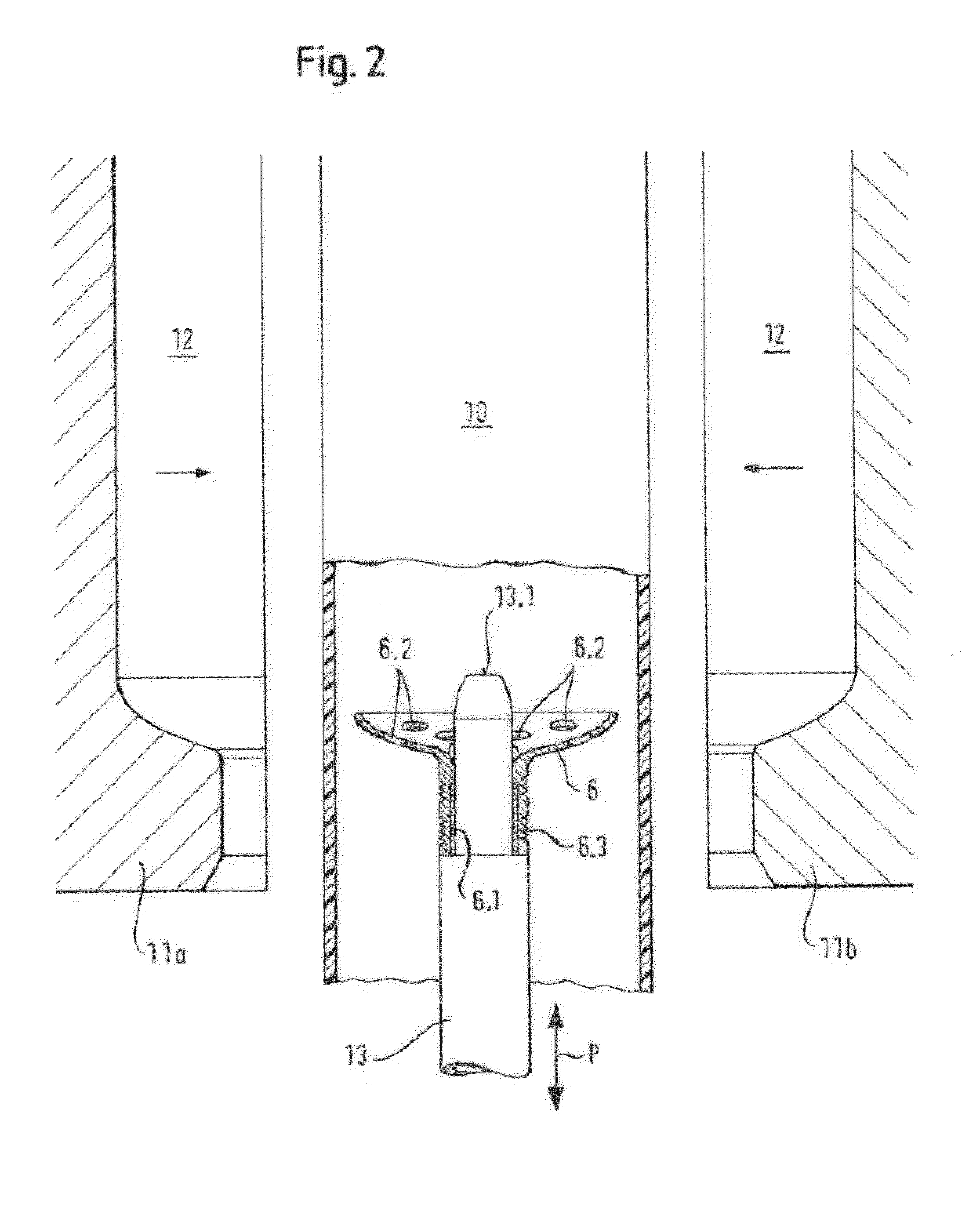
[0012]A method for producing a pressure tank blank from plastic may include the following steps: extruding a tube made of a thermoplastic from an extrusion die into an open blow mold, whose cavity is the negative of the blank; closing the blow mold and introducing compressed air to shape the blank; opening the blow mold after a cooling time and removing the blank. According to this method, pressure tank blanks of the present invention may be produced cost-effectively but having significantly improved strength when a metal insert having the inner contour of at least the shoulder of the blank is introduced into the corresponding area of the cavity when the blow mold is open and the tube, enclosing this metal insert, is extruded into the open blow mold.
[0016]If the blow mold is to be brought into a separate blowing station for shaping the blank in order to shorten the cycle time, a variant of the method is expedient in which the tube extruded into the open blow mold is kept open using partial vacuum in the area of its entry into the blow mold and is cut through above this, the blow mold is subsequently moved out of its position below the extrusion die into the separate blowing station, and a metal spherical cap having the inner contour of at least the floor of the blank is introduced from above into the open blow mold in the area of the cavity corresponding to the floor using a core rod which can be raised and lowered. This dispenses with additionally equipping the core rod carrying the metal insert with the metal spherical cap, allows the use of a correspondingly shorter core rod, and simultaneously permits the choice of implementing the lower or the upper core rod as a blow pin for shaping the blank.

Problems solved by technology

The problem of ensuring a tight connection between the tank and the valve, which naturally results in particular in tanks under high internal pressure, disappears if the metal insert has an internal thread for threadingly engaging the threads of a valve in the mouth area, because a metal internal thread is significantly more dimensionally stable and has greater long-term stability than an internal thread in a thermoplastic.

Method used


Image

  • Pressure Tank and Method and Blow-Molding Station for the Production Thereof
  • Pressure Tank and Method and Blow-Molding Station for the Production Thereof
  • Pressure Tank and Method and Blow-Molding Station for the Production Thereof

Examples


Embodiment Construction

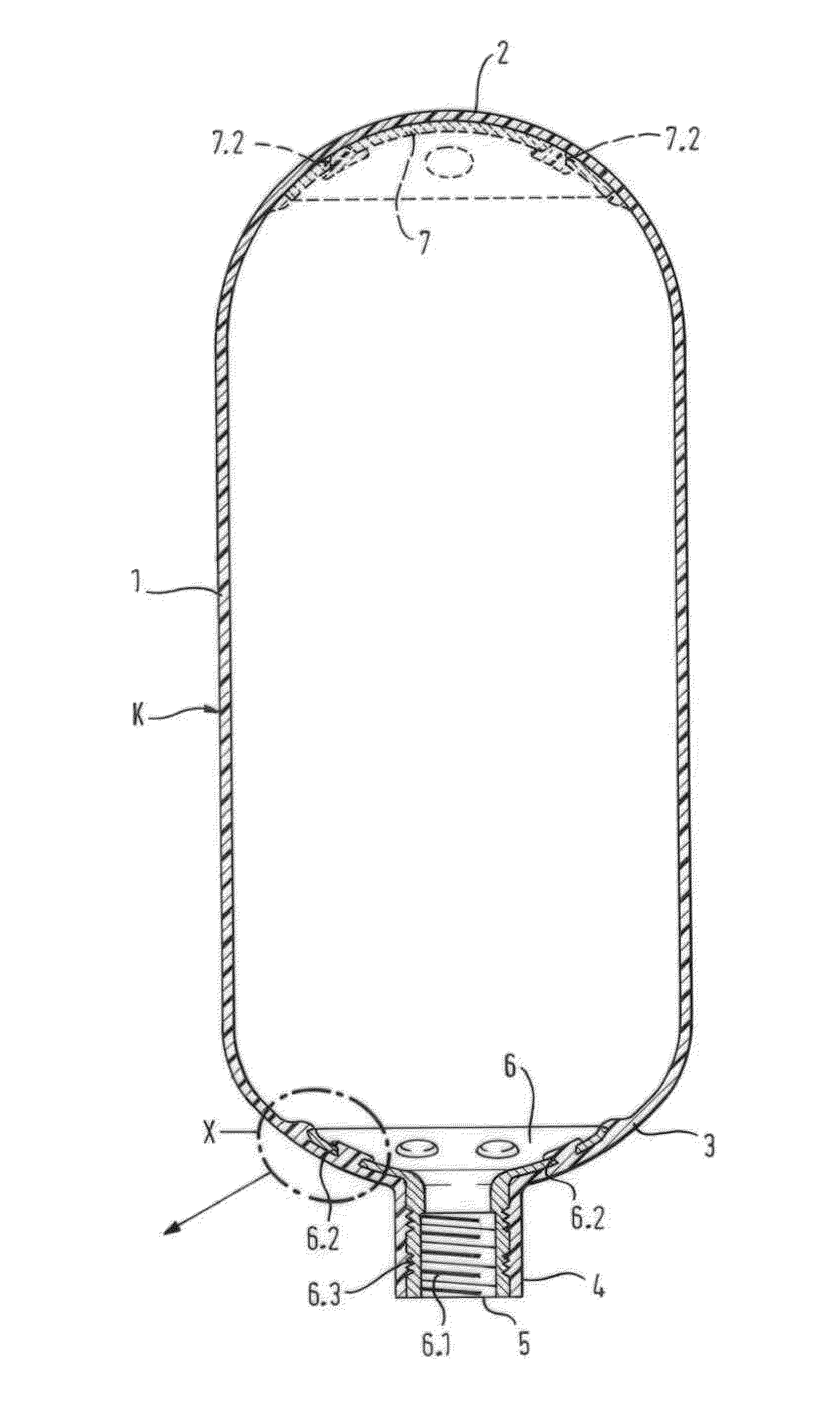
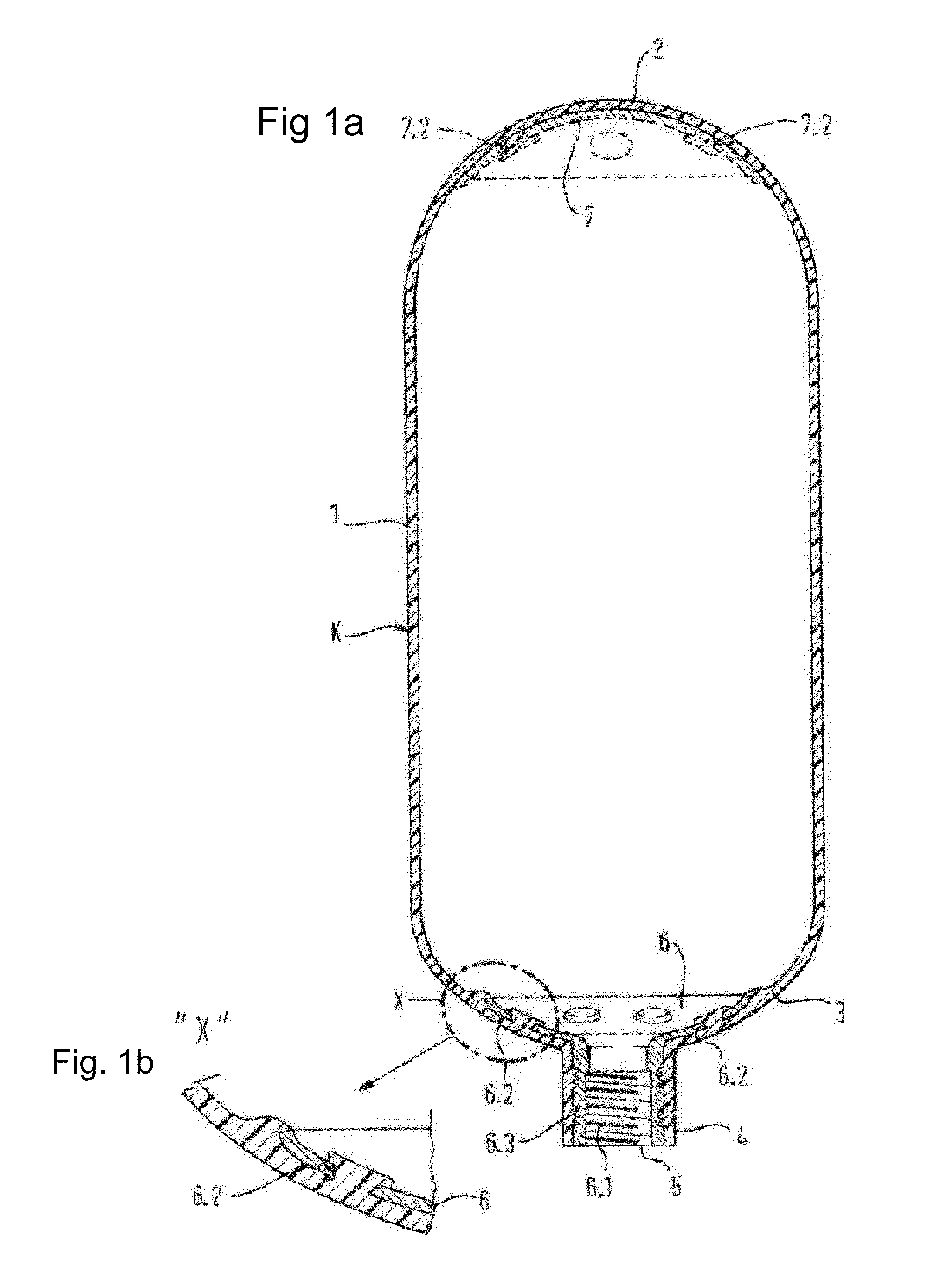
[0032]The pressure tank blank shown in longitudinal section in FIGS. 1a and 1b comprises an approximately bottle-shaped plastic hollow body, generated in a blow-molding method explained hereafter, made of an optionally multilayered thermoplastic K. The blank has a body 1 having circular cross-section, a floor 2 in the form of a spherical cap, and a shoulder 3, which merges into a neck 4 having an opening or mouth 5.

[0033]The blank includes an interior metal insert 6, which is enveloped by the thermoplastic K and extends up to the mouth 5 of the blank, in the area of its shoulder 3. The metal insert 6 has an internal thread 6.1 for screwing in a closure element (not shown), in particular a valve. The metal insert 6 can extend up to the transition of the shoulder 3 into the body 1, notwithstanding the illustration in FIG. 1.

[0034]In order to produce a reliable non-positive connection between the metal insert 6 and the plastic K, the metal insert 6 has openings 6.2 at least in the area...


PUM

PropertyMeasurementUnit
Pressureaaaaaaaaaa
Areaaaaaaaaaaa

Abstract

A pressure tank blank made of a thermoplastic, having a body, which merges via a shoulder into a neck and a mouth, which is implemented for screwing in a valve, is usable for gases under high pressure, if the blank has a metal insert enveloped by the plastic on the interior to reinforce at least the shoulder of the blank. This pressure tank blank may be produced in an extrusion blow-molding method. For this purpose, with open blow mold, a metal insert having the inner contour of at least the shoulder of the blank is introduced into the corresponding area of the cavity of the blow mold and the tube, enclosing this metal insert, is extruded into the blow mold, before it is closed.

Description

CROSS REFERENCE TO RELATED APPLICATIONS[0001]The present application claims priority under 35 U.S.C. §119 to Application No. DE 102009015964.9 filed on 2 Apr. 2009, entitled “Pressure Tank Blank and Method and Blow Molding Station for the production Thereof,” the disclosure of which is hereby incorporated by reference in its entirety.FIELD OF THE INVENTION[0002]The present invention relates to a pressure tank and, in particular, to a thermoplastic pressure tank blank having a reinforcing strip to prevent bursting of the blank under pressure. Furthermore, the invention relates to a method of forming the pressure tank blank, and a blow-molding station for the production of the pressure tank blank.BACKGROUND[0003]Pressure tanks based on a blank made of thermoplastic are used to store and discharge fluids such as propane or butane. At normal ambient temperatures, the typical equilibrium state results between the predominant liquid phase and the gas phase of the relevant fluid. Such cost...

Claims


Application Information

Patent Timeline
IPC IPC(8): B29C49/20B28B21/70B28B21/36B32B1/00
CPCB29C49/04Y10T428/1355B29C2049/2008B29C2049/2026B29C2049/2065B29C2049/2073B29L2031/7156F17C1/16F17C2201/0109F17C2201/054F17C2201/056F17C2203/012F17C2203/0617F17C2203/0619F17C2203/0636F17C2203/066F17C2203/0673F17C2205/0305F17C2205/0323F17C2205/0397F17C2209/2127F17C2209/232F17C2221/012F17C2221/035F17C2223/0153F17C2223/035F17C2223/036F17C2260/011Y02E60/321B29C49/20Y02E60/32
Inventor KOETKE, CLAUS-DIETER
Owner KUNSTVERARBEITUNG KOETKE
Learn More