Coaxial Cable Connector with RFI Sealing

Inactive Publication Date: 2010-10-07
PPC BROADBAND INC
View PDF18 Cites 83 Cited by
  • Summary
  • Abstract
  • Description
  • Claims
  • Application Information

AI Technical Summary

Benefits of technology

[0014]It is a further object of the present invention to provide a coaxial cable connector having structure to enhance RF coupling and sealing.
[0015]In the efficient attainment of these and other objects, the present invention provides a coaxial cable connector that will direct the electromagnetic field carryin

Problems solved by technology

However, as community television (CATV) systems have become more sophisticated in carrying many more channels of analog and digital information, the problems of interference caused by the ingress of radio frequency (RF) signals have grown.
However, because the conductive shield surrounding the foil typically has a braided construction to provide flexibility to the cable, the electrical signals travelling on the outer surface of

Method used


Image

  • Coaxial Cable Connector with RFI Sealing
  • Coaxial Cable Connector with RFI Sealing
  • Coaxial Cable Connector with RFI Sealing

Examples


Embodiment Construction

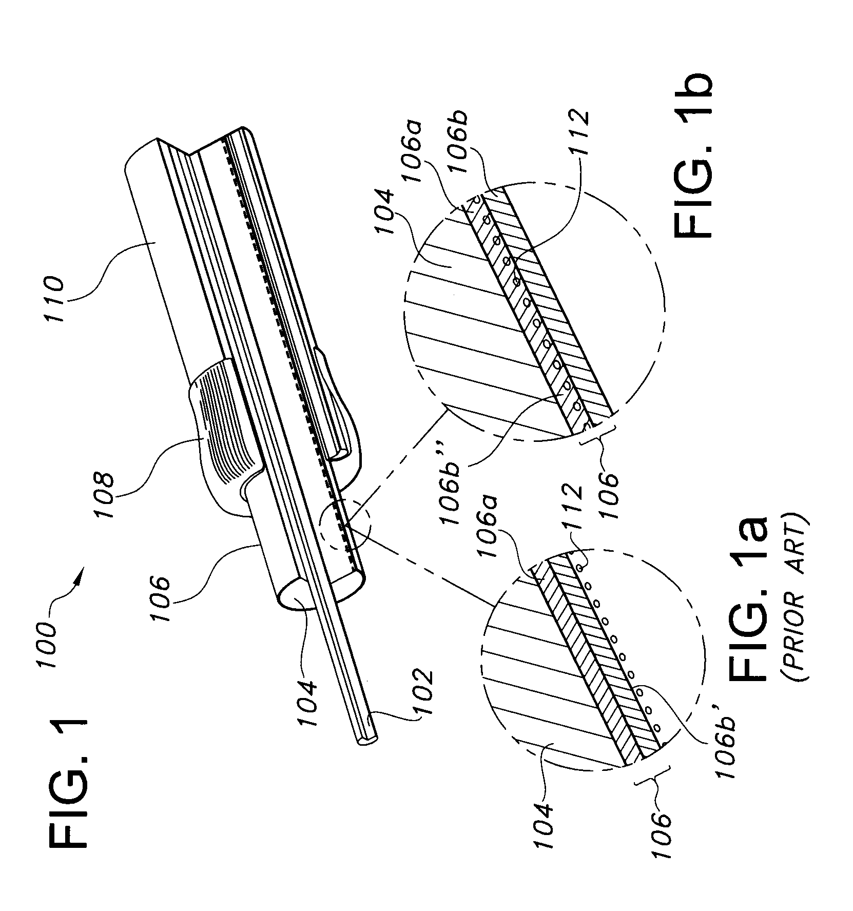
[0042]Referring first to FIG. 1, a conventional coaxial cable 100 includes an inner conductor 102 formed of copper or similar conductive material. Surrounding the inner conductor 102 is an insulator 104 formed of a dielectric material, such as a suitably insulative plastic. A metallic foil 106 is disposed over the insulator 104 and a metallic braided shield 108 is positioned in surrounding relationship around the foil covered insulator. Covering the braided shield 108 is an outer insulative jacket 110.

[0043]As discussed above, the conductive foil 106 is typically a laminated structure including a Mylar, or other insulative layer 106a and a conductive layer 106b. The foil 106 is wrapped around the dielectric core 104 so that the Mylar layer 106a forms the inner surface of the foil in contact with the core 104 and the conductive layer 106b forms the outer surface of the foil. As discussed above, the design of conventional coaxial cable connectors results in a signal flow 112 on the ou...


PUM

PropertyMeasurementUnit
Diameteraaaaaaaaaa
Electrical conductoraaaaaaaaaa

Abstract

A coaxial cable connector and method that will direct the electromagnetic field carrying the electrical signal in a coaxial cable to the inner surface of a conductive layer of the foil of the cable, as opposed to the outer surface. With the electrical signals traveling on the inner surface of the foil conductive layer, the foil conductive layer serves as a contiguous gap-free shield to prevent the ingress and/or egress of RFI.

Description

CROSS-REFERENCE TO RELATED APPLICATIONS[0001]This application claims the benefit of U.S. Provisional Application No. 61 / 166,956, filed on Apr. 6, 2009, the specification of which is incorporated by reference herein in its entirety for all purposes.BACKGROUND OF THE INVENTION[0002]The present invention relates generally to connectors for terminating coaxial cable. More particularly, the present invention relates to a coaxial cable connector having improved radio frequency integrity (RFI) sealing.[0003]It has long been known to use coaxial cable to carry communication signals from an external source to various electronic devices such as televisions, radios and the like. Conventional coaxial cables typically include a center conductor surrounded by an insulator. A conductive foil is disposed over the insulator and a braided conductive shield surrounds the foil covered insulator. An outer insulative jacket surrounds the shield.[0004]It is also well known to use connectors to terminate c...

Claims


Application Information

Patent Timeline
IPC IPC(8): H01R9/05H01R43/00
CPCH01R9/0524H01R24/40Y10T29/49123Y10T29/49174H01R2103/00
Inventor RADZIK, JACKTHOMAS, CHARLES
Owner PPC BROADBAND INC
Why Eureka
Try Eureka