Wearable Monitoring System

US20100256460A1Inactive Publication Date: 2010-10-07GENERAL ELECTRIC CO

Image

  • Wearable Monitoring System
  • Wearable Monitoring System
  • Wearable Monitoring System

Examples


Embodiment Construction

[0018]Specific embodiments are explained in the following detailed description making a reference to accompanying drawings. These detailed embodiments can naturally be modified and should not limit the scope of the invention as set forth in the claims.

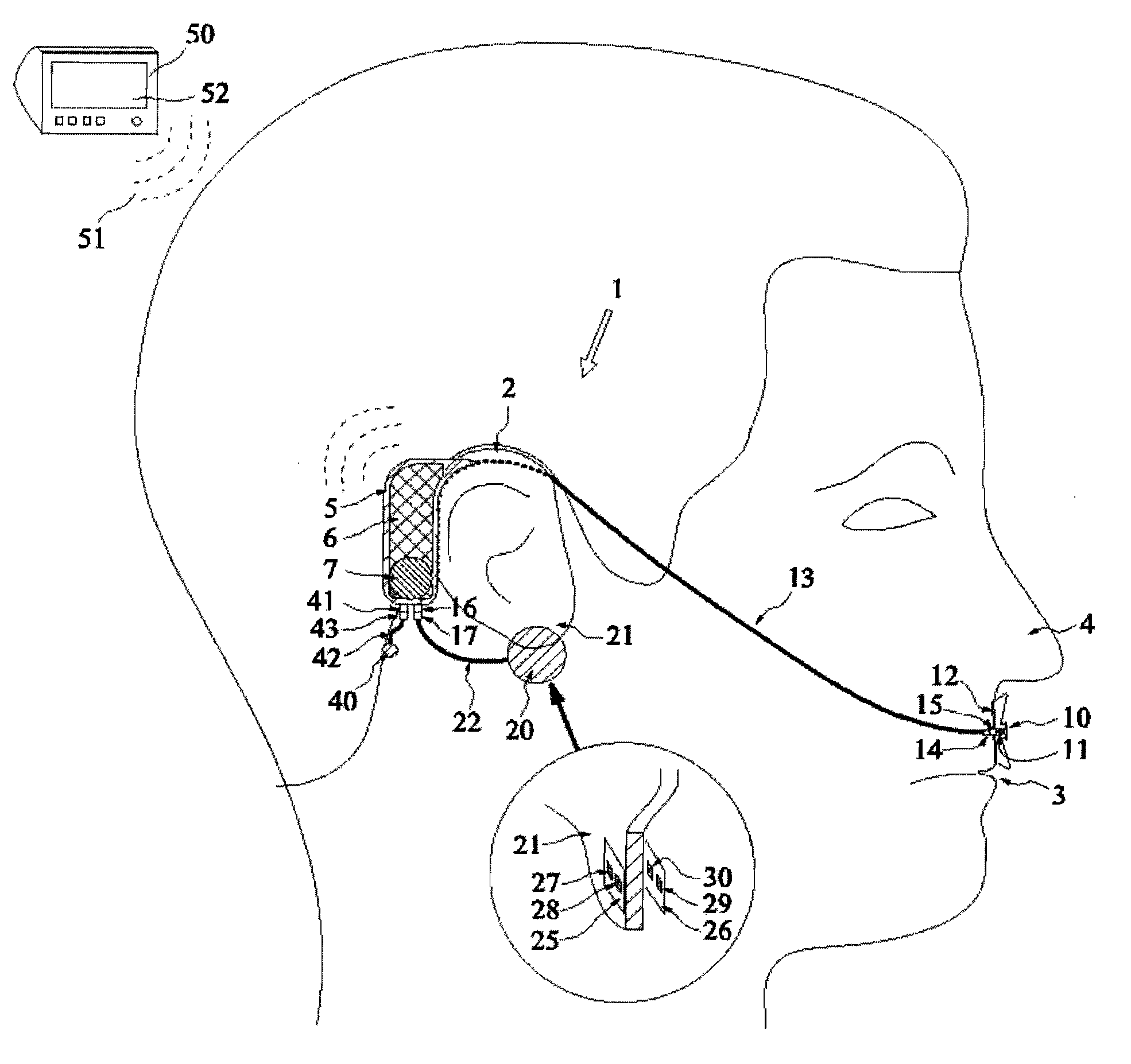
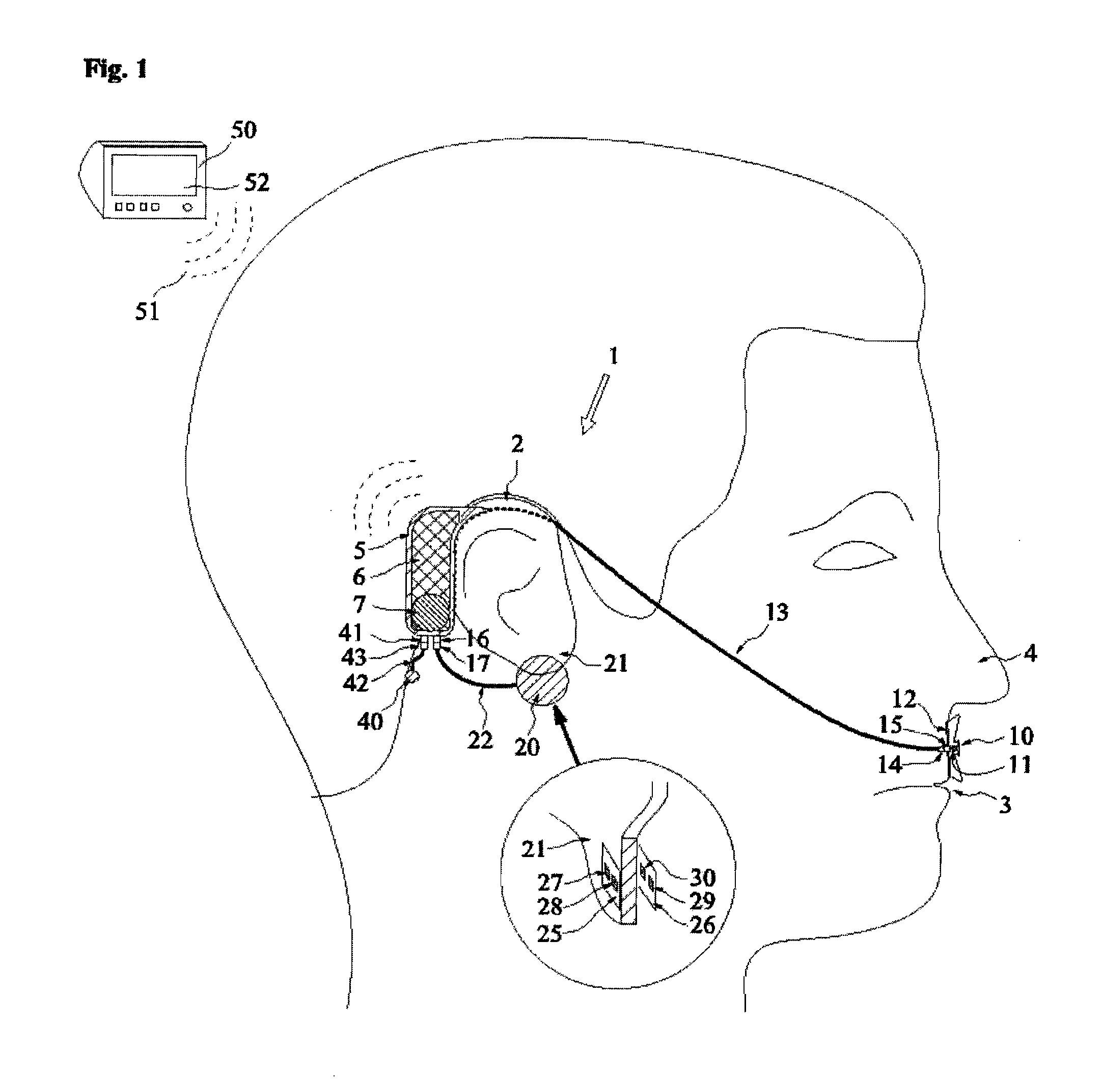
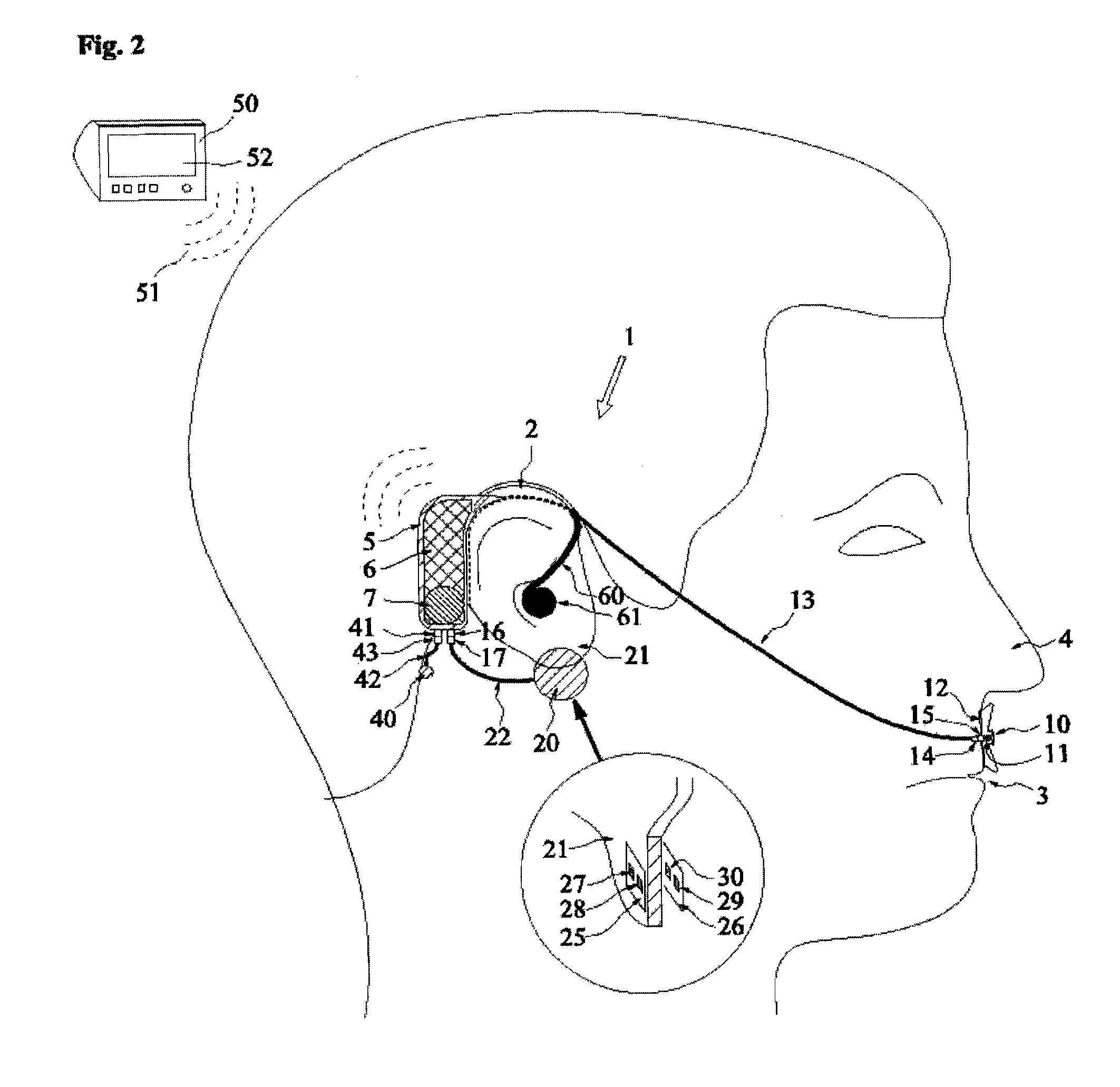
[0019]FIG. 1 shows a schematic side view of a wearable monitoring system 1 that may be wireless and can be used to collect a medical information from a subject. The monitoring system 1 can be placed on a side of a subject's head, over an ear 2, extending towards and close to a mouth 3 and a nose 4. The monitoring system 1 comprises a housing 5, which is installable to the subject's ear 2 or its vicinity. A suitable place for the housing is behind the subject's ear 2, similarly as commonly known hearing aid devices are placed. The housing 5 comprises electronics 6 for managing a signal acquired by at least one sensor 10, 20. The electronics 6 may comprise a radio frequency transceiver or similar wireless communication and signal process...


PUM


Abstract

A wearable monitoring system to collect medical information from a subject is disclosed herein. The wearable monitoring system includes a housing having electronics for managing a signal and which at least one housing is operatively connectable to at least one sensor for transmitting to the housing the signal acquired by the at least one sensor. The electronics of the housing is for managing the signal which is indicative of a condition of a respiration function and which housing is installable to the subject's ear or its vicinity.

Description

BACKGROUND OF THE INVENTION[0001]This disclosure relates generally to a wearable monitoring system to collect medical information from a subject.[0002]During apnea there is no movement of muscles of a respiration and a volume of lungs initially remains unchanged. Depending on an openness of airways there may not be a flow of a breathing gas between the lungs and an ambient during apnea. Apnea can be drug-induced (e.g., opiate toxicity), mechanically induced (e.g., strangulation or choking), or it can occur as a consequence of neurological disease or trauma as was explained above.[0003]Many people in hospital wards suffer from apnea, caused by opiates or other medicine. Patients may also have obstructive apnea, which is caused by a blockage in the airways, such as a thong or similar physical obstruction. Patients usually don't have any monitoring connected on as it is rather expensive and there are usually many patients in the ward. Furthermore, there is also a shortage of nursing pe...

Claims


Application Information

Patent Timeline
07 Oct 2010
Publication
US20100256460A1
IPC
A61B5/00; A61B5/08; A61B5/1455
CPC
A61B5/02055; A61B5/0878; A61B5/1455; A61B5/6838; A61B5/6815; A61B5/6816; A61B5/6817; A61B5/4818
Inventors
HAVERI, HEIKKI; LEPPALA, KRISTINA